1 allowed combinations of operation modes, 3 serial interface 0 and 1, Serial interface 0 modes – Maxim Integrated 71M6521BE Energy Meter IC Family Software User Manual
Page 122: Allowed combinations of operation modes, Serial interface 0 and 1
71M652X Software User’s Guide
Revision 1.7
TERIDIAN Proprietary
122 of 138
© Copyright 2005-2007 TERIDIAN Semiconductor Corporation
Bit
Symbol
Function
TCON.7 TF1
The Timer 1 overflow flag is set by hardware when Timer 1 overflows. This flag
can be cleared by software and is automatically cleared when an interrupt is
processed.
TCON.6
TR1
Timer 1 Run control bit. If cleared, Timer 1 stops.
TCON.5 TF0
Timer 0 overflow flag set by hardware when Timer 0 overflows. This flag can be
cleared by software and is automatically cleared when an interrupt is processed.
TCON.4
TR0
Timer 0 Run control bit. If cleared, Timer 0 stops.
TCON.3 IE1
Interrupt 1 edge flag is set by hardware when the falling edge on external pin
int1 is observed. Cleared when an interrupt is processed.
TCON.2 IT1
Interrupt 1 type control bit. Selects either the falling edge or low level on input
pin to cause an interrupt.
TCON.1 IE0
Interrupt 0 edge flag is set by hardware when the falling edge on external pin
int0 is observed. Cleared when an interrupt is processed.
TCON.0 IT0
Interrupt 0 type control bit. Selects either the falling edge or low level on input
pin to cause interrupt.
Table 6-25: The TCON Register Bit Functions
6.3.2.1
Allowed Combinations of Operation Modes
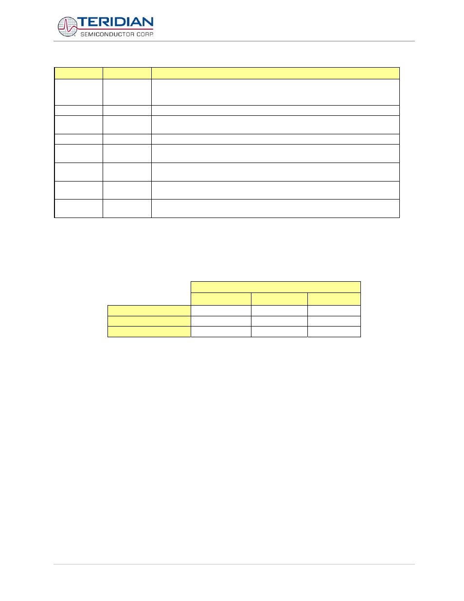
Table 6-25 specifies the combinations of operation modes allowed for timer 0 and timer 1.
Timer 1
Mode 0
Mode 1
Mode 2
Timer 0 - mode 0
YES
YES
YES
Timer 0 - mode 1
YES
YES
YES
Timer 0 - mode 2
Not allowed
Not allowed
YES
Table 6-26: Timer Modes
6.3.3 Serial Interface 0 and 1
The serial buffer consists of two separate registers, a transmit buffer and a receive buffer.
Writing data to the Special Function Register S0BUF or S1BUF sets this data in the serial output buffer and starts
transmission. Reading from the S0BUF or S1BUF reads data from the serial receive buffer. The serial port can
simultaneously transmit and receive data. It can also buffer 1 byte at receive, preventing the receive data from being
lost if the MPU reads the first byte before transmission of the second byte is completed.
Serial Interface 0 Modes
The Serial Interface 0 can operate in 4 modes:
Mode 0
Pin rxd0 serves as an input and an output. Txd0 outputs the shift clock. 8 bits are transmitted starting with the LSB.
The baud rate is fixed at 1/12 of the MPU frequency. Reception is initialized in Mode 0 by setting the flags in S0CON as
follows: RI0=0 and REN0=1. In other modes, when REN0 = 1, a start bit initiates receiving serial data.