Serial interface 1 modes – Maxim Integrated 71M6521BE Energy Meter IC Family Software User Manual
Page 124
71M652X Software User’s Guide
Revision 1.7
TERIDIAN Proprietary
124 of 138
© Copyright 2005-2007 TERIDIAN Semiconductor Corporation
SM0
SM1
Mode
Description
Baud Rate
0 0 0
shift
register
Fclk/12
0 1 1
8-bit
UART Variable
1
0
2
9-bit UART
Fclk/32 or /64
1 1 3
9-bit
UART Variable
Table 6-29: Serial Port 0 Modes
Note: The speed in Mode 2 depends on the SMOD bit in the Special Function Register PCON when SMOD = 1,
Fclk/32.
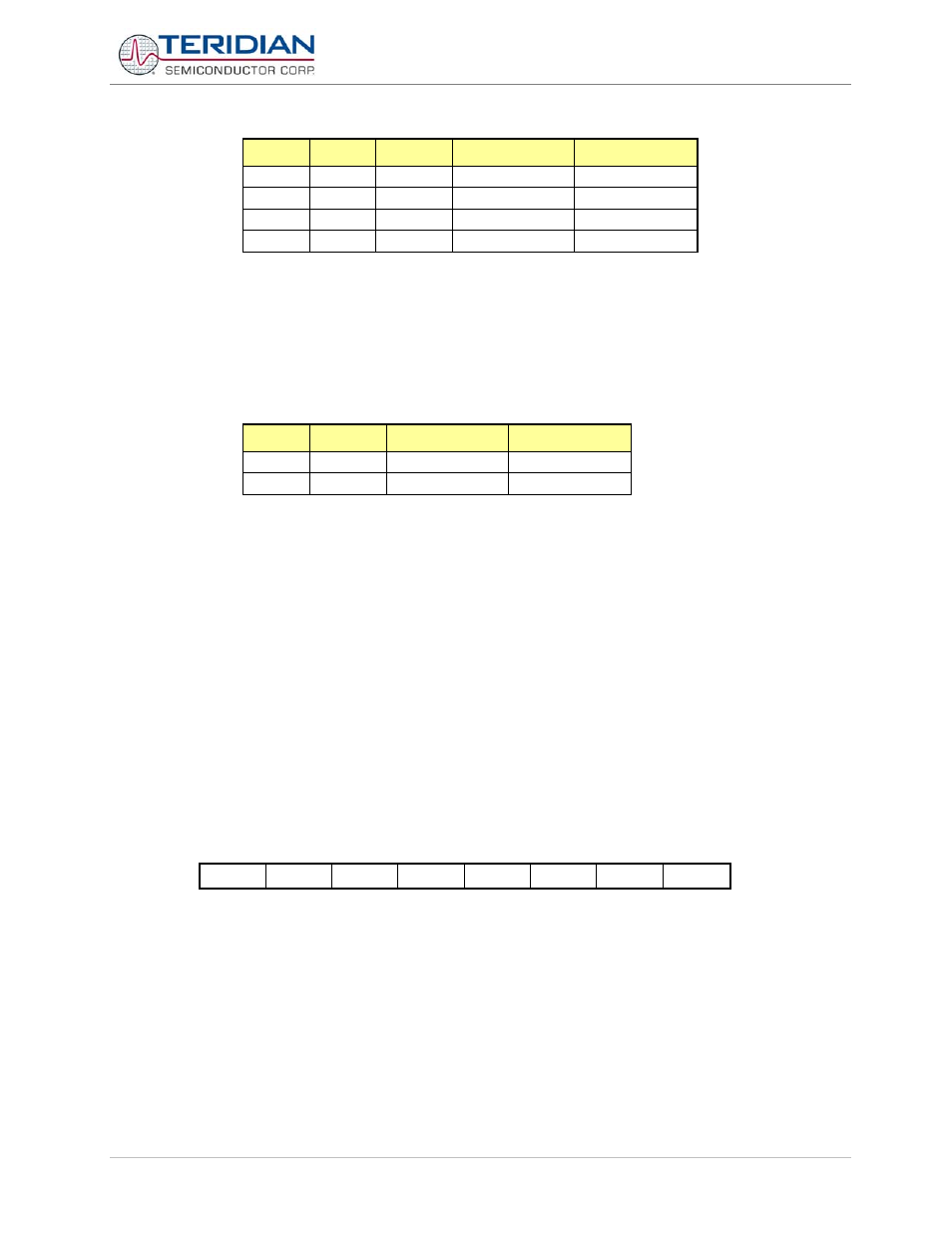
Serial Interface 1 Modes
The Serial Interface 1 can operate in 2 modes:
SM
Mode
Description
Baud Rate
0 A
9-bit
UART
variable
1 B
8-bit
UART
variable
Table 6-30: Serial 1 Modes
Mode A
This mode is similar to Mode 2 and 3 of serial interface 0. 11 bits are transmitted or received: a start bit (0), 8 data bits
(LSB first), a programmable 9
th
bit, and a stop bit (1). The 9
th
bit can be used to control the parity of the serial interface:
at transmission, bit tb81 in S1CON is output as the 9th
bit, and at receive, the 9th
bit affects rb81 in the Special
Function Register S1CON. The only difference between Mode 3 and A is that in Mode A, only the internal baud rate
generator can be use to specify baud rate.
Mode B
This mode is similar to Mode 1 of serial interface 0. Pin rxd1 serves as an input, and txd1 serves as a serial output. No
external shift clock is used. 10 bits are transmitted: a start bit (always 0), 8 data bits (LSB first), and a stop bit (always
1). On receive, a start bit synchronizes the transmission. 8 data bits are available by reading S1BUF, and the stop bit
sets the flag rb81 in the Special Function Register S1CON. In mode B, the internal baud rate generator specifies the
baud rate.
Serial Interface 1 Control Register (S1CON).
The function of the serial port depends on the setting of the Serial Port Control Register S1CON.
MSB
LSB
SM - SM21
REN1
TB81
RB81
TI1 RI1
Table 6-31: The S1CON Register