Interrupt request register (t2con), 4 interrupt priority level structure, Interrupt priority level structure – Maxim Integrated 71M6521BE Energy Meter IC Family Software User Manual
Page 131
71M652X Software User’s Guide
Revision 1.7
TERIDIAN Proprietary
131 of 138
© Copyright 2005-2007 TERIDIAN Semiconductor Corporation
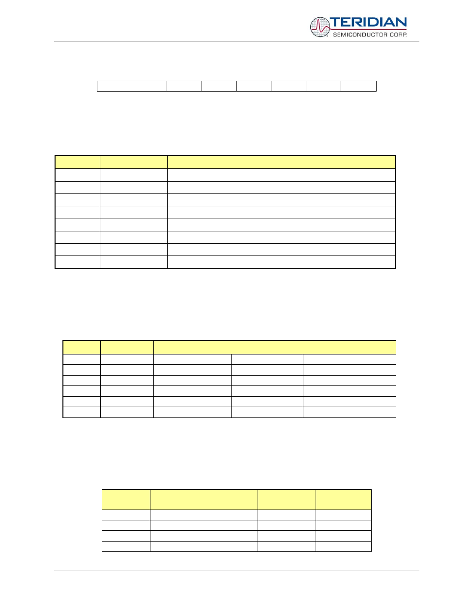
Interrupt Request register (T2CON)
MSB
LSB
I3FR
I2FR
Table 6-51: The T2CON Register
Bit
Symbol
Function
T2CON.7
T2CON.6
I3FR
This bit controls the polarity of external interrupt 3
T2CON.5
I2FR
This bit controls the polarity of external interrupt 2
T2CON.4
T2CON.3
T2CON.2
T2CON.1
T2CON.0
Table 6-52: The T2CON Bit Functions
6.3.5.4
Interrupt Priority Level Structure
All interrupt sources are combined in groups, as shown in Table 6-52. The priority of each group is controlled by the
bits of SFR registers IP1 and IP0.
Group
IP Bits
Affected Interrupts
0
Ip1.0, IP0.0
External interrupt 0
UART 1 interrupt
-
1
Ip1.1, IP0.1
Timer 0 interrupt
-
External interrupt 2
2
Ip1.2, IP0.2
External interrupt 1
-
External interrupt 3
3
Ip1.3, IP0.3
Timer 1 interrupt
-
External interrupt 4
4
Ip1.4, IP0.4
UART 0 interrupt
-
External interrupt 5
5
IP1.5, IP0.5
-
-
External interrupt 6
Table 6-53: Priority Level Groups
Each group of interrupt sources can be programmed individually to one of four priority levels by setting or clearing one
bit in the special function register IP0 and one in IP1.
If requests of the same priority level are received simultaneously,
an internal polling sequence determines which request is serviced first.
The functionality and edge polarity of the external interrupts are described in Table 6-51.
External
Interrupt
Connection
Polarity
Flag Reset
0
Digital I/O High Priority
see DIO_Rx
automatic
1
Digital I/O Low Priority
see DIO_Rx
automatic
2 Comparator
falling automatic
3 CE_BUSY
falling automatic