5 interrupt sources and vectors, External interrupt edge detect, Interrupt sources and vectors – Maxim Integrated 71M6521BE Energy Meter IC Family Software User Manual
Page 133
71M652X Software User’s Guide
Revision 1.7
TERIDIAN Proprietary
133 of 138
© Copyright 2005-2007 TERIDIAN Semiconductor Corporation
External interrupt 1
External interrupt 3
Timer 1 interrupt
External interrupt 4
UART 0 interrupt
External interrupt 5
External interrupt 6
Table 6-59: Polling Sequence
6.3.5.5
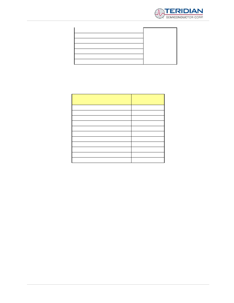
Interrupt Sources and Vectors
The vectors associated with each interrupt source are displayed in Table 6-59.
Interrupt Request Flags
Interrupt Vector
Address
IE0 – External interrupt 0
0003H
TF0 – Timer 0 interrupt
000BH
IE1 – External interrupt 1
0013H
TF1 – Timer 1 interrupt
001BH
RI0/TI0 – UART 0 interrupt
0023H
RI1/TIi1 – UART 1 interrupt
0083H
IEX2 – External interrupt 2
004BH
IEX3 – External interrupt 3
0053H
IEX4 – External interrupt 4
005BH
IEX5 – External interrupt 5
0063H
IEX6 – External interrupt 6
006BH
Table 6-60: Interrupt Vectors
External Interrupt Edge Detect
The external interrupts 4, 5 and 6 are activated by a positive transition. The external source must hold the request pin
low (high for int2 and int3, if it is programmed to be negative transition-active) for at least one MPU clock period.
Afterwards, it must be held high (low) for at least one MPU clock period to ensure the transition is recognized and the
corresponding interrupt request flag is set.