1 baud rate generator, Baud rate generator – Maxim Integrated 71M6521BE Energy Meter IC Family Software User Manual
Page 125
71M652X Software User’s Guide
Revision 1.7
TERIDIAN Proprietary
125 of 138
© Copyright 2005-2007 TERIDIAN Semiconductor Corporation
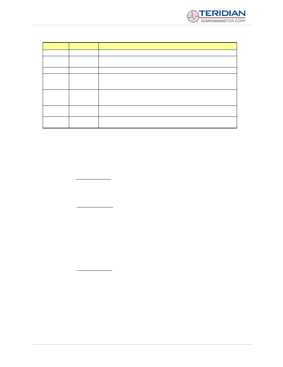
Bit
Symbol
Function
S1CON.7
SM
Sets baud rate
S1CON.5
SM21
Enables the multiprocessor communication feature (see description
above).
S1CON.4
REN1
If set, enables serial reception. Cleared by software to disable reception.
S1CON.3 TB81
The
9
th
transmitted data bit in Mode A. Set or cleared by the MPU,
depending on the function it performs (parity check, multiprocessor
communication etc.)
S1CON.2 RB81
In
Modes
2 and 3, it is the 9
th
data bit received. In Mode B, if sm21 is 0,
rb81 is the stop bit. In Mode 0 this bit is not used. Must be cleared by
software
S1CON.1
TI1
Transmit interrupt flag, set by hardware after completion of a serial
transfer. Must be cleared by software.
S1CON.0
RI1
Receive interrupt flag, set by hardware after completion of a serial
reception. Must be cleared by software
Table 6-32: The S1CON Bit Functions
6.3.3.1
Baud Rate generator
Serial 0 modes 1 and 3 only (Fclk = MPU clock rate):
Timer1 baud rate generator (WDCON.7 = 0)
)
1
256
(
384
2
mod
th
F
baudrate
s
clk
−
⋅
⋅
=
Internal baud rate generator (WDCON.7 = 1)
)
0
2
(
64
2
10
mod
rel
s
F
baudrate
s
clk
−
⋅
⋅
=
Note: s0rel is a 10 bit value formed by concatenating S0RELH and S0RELL as follows:
s0rel = {S0RELH.[1:0], S0RELL.[7:0]}
Serial 1 all modes: (Fclk = MPU clock rate):
Internal baud rate generator only
)
1
2
(
32
10
rel
s
F
baudrate
clk
−
⋅
=
Note: s1rel is a 10 bit value formed by concatenating S1RELH and S1RELL as follows:
s1rel = {S1RELH.[1:0], S1RELL.[7:0]}