5 managing mission and battery modes, Managing mission and battery modes, Figure 5-21: power-up sequence – Maxim Integrated 71M6521BE Energy Meter IC Family Software User Manual
Page 67
71M652X Software User’s Guide
Revision 1.7
TERIDIAN Proprietary
67 of 138
© Copyright 2005-2007 TERIDIAN Semiconductor Corporation
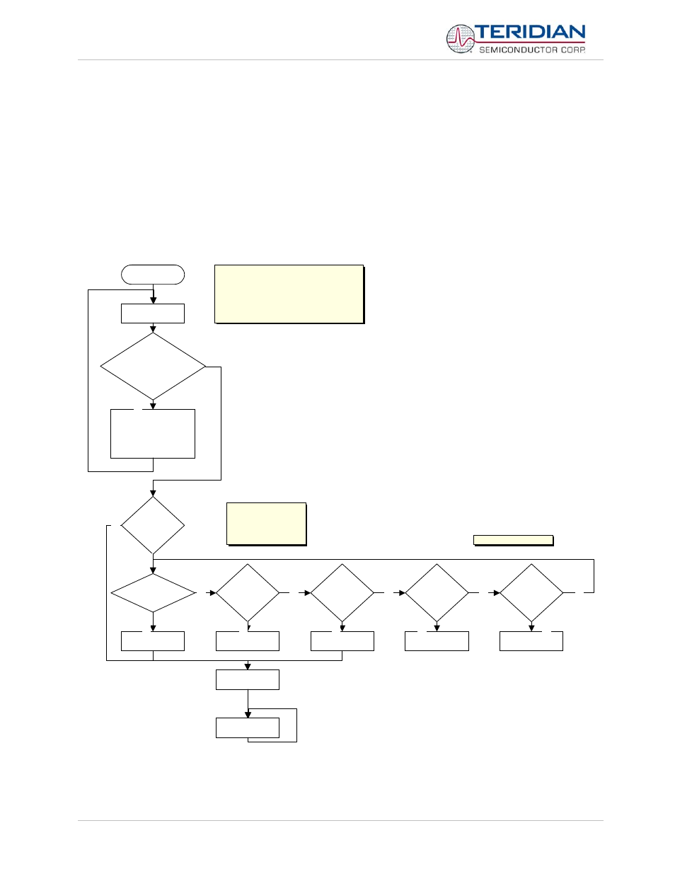
5.5 MANAGING MISSION AND BATTERY MODES
After a reset or power up, the processor must first decide what mode it is in and then take the appropriate action. It is
useful to concentrate all activities related to power modes and reset into one centralized module. The Demo Code
revision 4.7a does the switching of modes in the main() routine, based on decisions made in batmodes_20.c. Figure
5-21 shows the actions taken by the Demo Code and chip hardware after entering the main() routine. The code uses
the following inputs and flags to determine which mode to enter:
•
Battery mode enable jumper (see the DBUM for a detailed description of this input)
• PLL_OK
flag
• RESET
input
• PB
input
main
Start here:
1. On power up
2. On HWDT Overflow
3. If PB pressed
4. On wake up from LCD or Sleep Modes
5. If Reset Button Pressed
6. Soft Reset function invoked.
Restart Hardwrare
WDT
Check if HWDT
has overflowed ?
Set Status register
Clear Overflow flag
Invoke Soft Reset
Is battery
mode
enabled?
Is PLL ok ?
Already in
Brownout
mode?
Is Reset
Button
Pressed?
Is Push
Button
Pressed?
Mission mode
Sleep mode
Brownout Mode
LCD mode
Initialise Main
Run Main Loop
Sleep mode
Is V3P3
Sys
Present ?
On power up, will remain in
this loop till PLL ok flag is
set and "Brownout
interrupt" occurs which
invokes a "Soft Reset"
Checked by Hardware
N
N
N
N
Y
Y
N
Y
N
Y
Y
Y
Y
N
Figure 5-21: Power-Up Sequence