Maxim Integrated 71M6521BE Energy Meter IC Family Software User Manual
Page 123
71M652X Software User’s Guide
Revision 1.7
TERIDIAN Proprietary
123 of 138
© Copyright 2005-2007 TERIDIAN Semiconductor Corporation
Mode 1
Pin rxd0 serves as an input, and txd0 serves as a serial output. No external shift clock is used. 10 bits are transmitted:
a start bit (always 0), 8 data bits (LSB first), and a stop bit (always 1). On receive, a start bit synchronizes the
transmission. 8 data bits are available by reading S0BUF, and the stop bit sets the flag RB80 in the Special Function
Register S0CON. In mode 1 either the internal baud rate generator or timer 1 can be use to specify the baud rate.
Mode 2
This mode is similar to Mode 1, with two differences. The baud rate is fixed at 1/32 or 1/64 of the oscillator frequency
and 11 bits are transmitted or received: a start bit (0), 8 data bits (LSB first), a programmable 9
th
bit, and a stop bit (1).
The 9
th
bit can be used to control the parity of the serial interface: at transmission, bit TB80 in S0CON is output as the
9
th
bit, and at receive, the 9
th
bit affects RB80 in the Special Function Register S0CON.
Mode 3
The only difference between Mode 2 and Mode 3 is that in Mode 3, either the internal baud rate generator or timer 1
can be use to specify the baud rate.
Note: The common FLAG protocol requires the data format to be 7E1. This can be implemented using one of the 8-bit
modes, where the MSB (bit 0) is the parity bit. In this mode, the MPU calculates parity
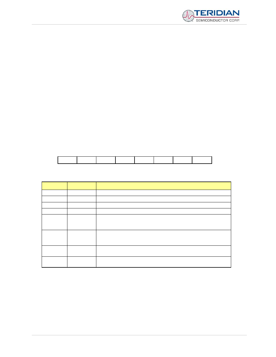
Serial Interface 0 Control Register (S0CON).
The function of the serial port 0 depends on the setting of the Serial Port Control Register S0CON.
MSB
LSB
SM0 SM1 SM20
REN0 TB80 RB80 TI0 RI0
Table 6-27: The S0CON Register
Bit
Symbol
Function
S0CON.7
SM0
Sets baud rate
S0CON.6
SM1
Sets baud rate
S0CON.5 SM20
reserved
S0CON.4
REN0
If set, enables serial reception. Cleared by software to disable reception.
S0CON.3 TB80
The
9
th
transmitted data bit in Modes 2 and 3. Set or cleared by the MPU,
depending on the function it performs (parity check, multiprocessor
communication etc.)
S0CON.2 RB80
In
Modes
2 and 3 it is the 9
th
data bit received. In Mode 1, if SM20 is 0,
RB80 is the stop bit. In Mode 0 this bit is not used. Must be cleared by
software
S0CON.1
TI0
Transmit interrupt flag, set by hardware after completion of a serial
transfer. Must be cleared by software.
S0CON.0
RI0
Receive interrupt flag, set by hardware after completion of a serial
reception. Must be cleared by software
Table 6-28: The S0CON Bit Functions