Instructions that affect flags, 3 80515 hardware description, 80515 hardware description – Maxim Integrated 71M6521BE Energy Meter IC Family Software User Manual
Page 117
71M652X Software User’s Guide
Revision 1.7
TERIDIAN Proprietary
117 of 138
© Copyright 2005-2007 TERIDIAN Semiconductor Corporation
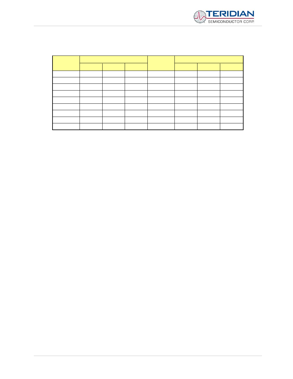
Instructions that Affect Flags
Instruction
Affected Flag
Instruction
Affected Flag
C
OV
AC
C
OV
AC
ADD X X X CLR
C 0
ADDC X X X CPL
C X
SUBB
X
X
X
ANL C, bit
X
MUL
0
X
ANL C, /bit
X
DIV
0
X
ORL C, bit
X
DA
X
ORL C, /bit
X
RRC
X
MOV C, bit
X
RLC X CJNE X
SETB
C
1
Table 6-17: Instructions Affecting Flags
Note: Operations affecting the PSW or bits in the PSW will also affect flag settings
6.3 80515 HARDWARE DESCRIPTION
The 80515 core implemented in the 71M652X chips consists of:
1. Control processor unit (CPU), also referred to as MPU throughout this document
2. Arithmetic-logic
unit
3. Clock control unit
4. Memory control unit
5. RAM and SFR control unit
6. Ports registers unit
7. Timer 0, 1 unit
8. Serial 0, 1 interfaces
9. Watchdog
timer
10. Interrupt service routine unit