Job o – combustion setup procedure – LAARS NeoTherm NTV1000 - Install and Operating Manual User Manual
Page 79
NeoTherm Boilers and Water Heaters
Page 75
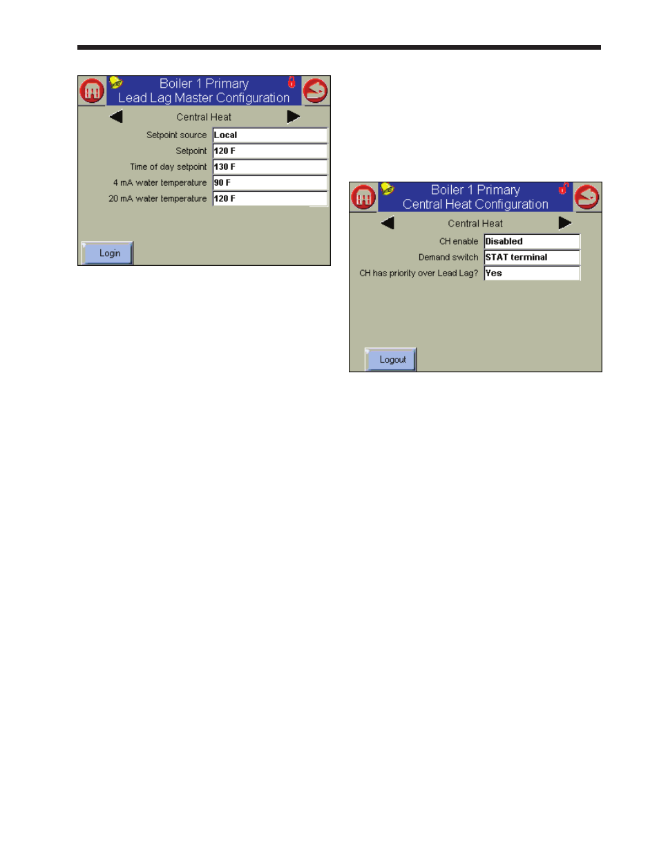
Fig. 98 – Lead Lag Central Heat Configuration
3. Change the 4 mA water temperature to match
the lowest water temperature setting on the
Building Automation System or multiple boiler
control.
4. Change the 20mA water temperature to match
the highest water temperature setting on the
Building Automation System or Multiple boiler
control.
Job n - Building automation or multiple
Boiler 4-20 ma modulation Control
(This is an individual function – do this on each of the controls.)
In this type of installation, the fan speed of each
boiler is changed or modulated by a source outside
of the boiler. All active burners must operate at the
same modulation rate while operating. The system
will not operate correctly if some of the burners are
being asked to operate at full rate while other burners
are operating at minimum rates.
1. On each controller in the system, check
terminals 5 and 6 on TB7 to ensure that the
System sensor is not connected. (For this type
of operation, the Lead/Lag system is disabled.)
2. Connect the 4-20 mA input to each controller in
the system.
• On the Primary controller in each boiler,
connect to terminals 3 and 4 on TB7.
• On the Secondary controller in each boiler,
connect to terminals 7 and 8 on TB7.
3. Enable a central heat call for each control
on the system. This function must be set up
for each controller separately. This function
operates outside of the Lead/Lag system.
How to get there – Central Heat Enable
Home Page
Boiler 1 Primary Screen
1 Primary Configuration Screen
4. Fig. 99 shows the setup screen.
Fig. 99 - Central Heat Configuration
5. Enable the Central Heat function on the top
line. Give the CH function the priority using
the lower line.
Job o – Combustion Setup Procedure
(These are individual functions. Do the combustion setup for
each of the burners.)
In this section, we will explain how to set up the gas
valve so both burners in each boiler run efficiently
at both the High Fire and Low Fire conditions. As
we said, a boiler includes two controllers (Primary
and Secondary), which control two burners (Primary
and Secondary). See Fig. 100. Each burner has
a separate gas valve, and each of these must be
set up separately. Here’s a quick summary of the
procedure:
•
You shut off one controller/burner
combination, and work with the other.
•
You set the working burner to run at High
Fire, and adjust the gas valve to get the correct
CO
2
reading.
•
Next you set the same burner to run at Low
Fire, and make another adjustment on the gas
valve to get the desired CO
2
reading.