6b.3 cold water make-up, 6b.4 freeze protection, 6b.5 suggested piping schematics – LAARS NeoTherm NTV1000 - Install and Operating Manual User Manual
Page 30: 6b.6 suggested pumps, Laars heating systems, 6b.3 ntv cold water make-up, 6b.4 ntv freeze protection, 6b.5 ntv suggested piping schematics, 6b.6 ntv suggested pumps
LAARS Heating Systems
Page 26
6B.3 ntV Cold Water make-Up
The cold water make-up may be connected to the
tank or to the inlet of the boiler as shown in Figures
16-18. Install back flow preventers and shut offs
where needed or required by code.
6B.4 ntV freeze Protection
The NTV unit must never be installed outdoors
in a location which may experience freezing
temperatures. If installed indoors, and there is an
event such as a power outage, component failure or
other issue when freezing is likely, the heater and
system must be drained to avoid the risk of damage
due to freezing. Glycol must NOT be used in
volume water heating applications.
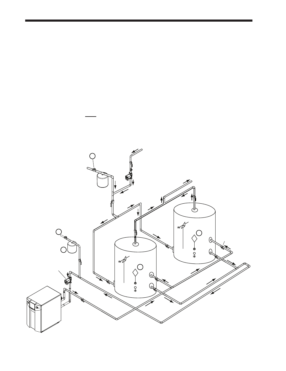
fig. 17 - DHW Piping - one Heater, two Vertical tanks
6B.5 ntV Suggested Piping
Schematics
Figures 16-18 show suggested piping
configurations for NTV boilers. These diagrams
are only meant as guides. All components or
piping required by local code must be installed.
6B.6 ntV Suggested Pumps
See Table 8 for water flow and head
requirements.
noteS:
1. Optional CWMU & recirculation line location.
2. Locate the NTV DHW sensor or remote aquastat well
in lower 1/3 of tank.
3. Back flow preventer may be required - check local
codes.
4. Thermal expansion tank may be required -
check local codes.
5.
Caution: Pump sizing must be based upon water
hardness at job site.
Cold water
supply
3
Expansion
tank
1
4
Pump
TPRV
2
Building
return
Ball valve
(typical)
TPRV
2
Supply
WarnInG: This drawing shows
suggested piping configuration and
valving. Check with local codes and
ordinances for additional requirements.