Interlogix Monitor XL Advanced Installation Guide User Manual
Page 7
21-3602E rev1.5
Monitor xL™ Advanced Installation Guide
1
Entering and Understanding
Advanced Configurations
Logon to the system as a service user. E.g. Default
ID: “000”, service user PIN: “2482” or “7378” if the
panel has communicated with the Director
Software.
NOTE: If the system Feature Set (S00200) is 5 or
greater, keypad programming can not be done.
Programming can only be done with the Director
Software.
NOTE: Default MASTER (end) USER code is ID 01
or 001, PIN 7793.
LCD Keypad Screen
When the control box
tamper is activated, a
service user has
Service
Enter PIN: _ _ _ _
the authority to access system programming
.
Using the left and right
arrow screen scrolling
keys on the keypad
Menu Options
◄ Config ►
Ok
scroll the menus until
Config
is displayed. Press
Ok.
“Config method” will display. Select “Advanced” with
the arrow keys and press Ok.
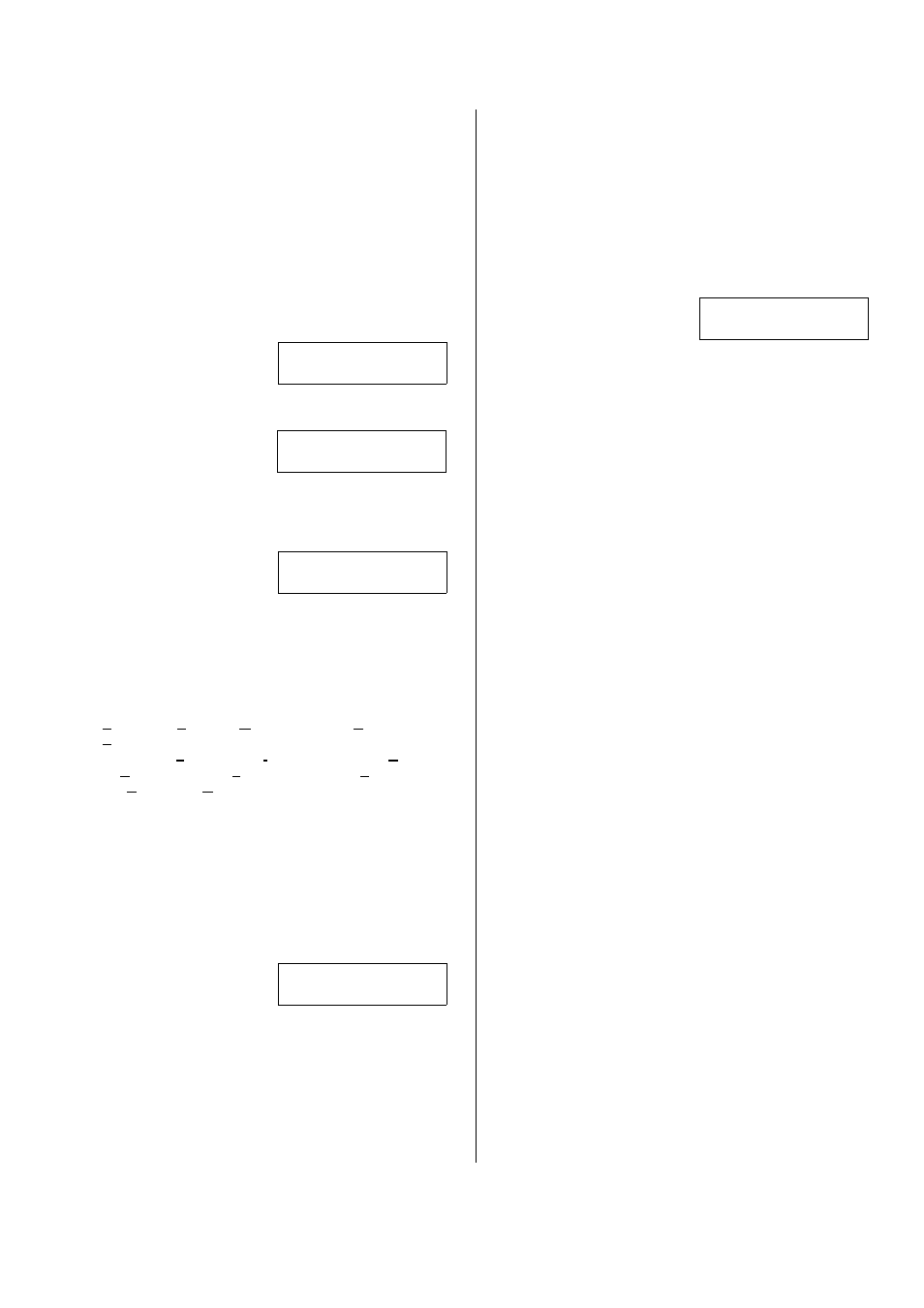
The screen that begins
Advanced programming
will display.
S001:00 E-05Q34
OK +Group-
S001:00: this is the start of the System program section.
Each of the program sections begin with a letter. The
next 3 digits (e.g. “001”) represent the first program
section for System programming. The next 2 digits (e.g.
“00” after the colon) represent a sub programming
section of this main system program section.
The letters for each of the programming sections are: S:
System; A: Areas; M: Modules; P: Input Points; E:
Equipment/Pseudo points; B: Programmable Outputs;
L: Authority Levels; I: ProfIle; W: User Edit; U: Users;
H: Holidays; D: Schedules; T: Custom Pt Type; R:
DooRs; G: Area Group; Z: Shared Data Groups (Users
and Holidays).
E-05Q34: the version of the main controller firmware.
+Group- : Using the middle or right down arrow keys
this term’s arrows are pointing to will scroll forward or
backward through the various program sections
(Groups). It will change the program section letter &
display that section’s program selections for the same
programming and sub programming section.
OK: Pressing the button below OK will enter the
programming section displayed.
A sub programming
section can display
several defaulted
□
.
□
.0.
□
.
1
.
□ □
Save S002:1
selections that will affect the way the system operates.
These selections can be changed to customize the
system operation. A box “ □
”
represents that a
programming selection has been disabled. A check mark
“
“
means that it is enabled. With the cursor flashing
under a specific selection, the selection can be toggled
back and forth from a box to a check mark by pressing
any key on the keypad.
Other entries are numerical and with the cursor flashing
under them they can be changed by pressing the
desired number entry on the keypad from available
selections. When entering a sub programming section
and all its various selections, the section displayer (e.g.
S002:1) appears in the lower right corner of the
screen.
When a selection has bee changed, always press the
button below
Save to retain the change.
A program section with a
down arrow in its section
displayer means if the
201
.
01
.
01
. . . .
Save ? P0010
down arrow button beneath it is pressed, the screen will
change to the next input, output etc
. and the same
program selections for it.
Pressing the keypad button below “
? “ when it
displays in a screen, will cause a momentary
screen to display related information. E.g. an input
or output number associated with a module will
display the module’s number (i.e. module # XX),
what type it is (e.g. Point Expander module), the
module’s serial number and its input or output
number range. Pressing the button below “
“ will
display information about a specialized module
such as RF wireless or a printer module.