Temporarily install hinges and torque rods – Great Planes F-14 60 Kit - GPMA0435 User Manual
Page 9
D D 5. Using a sanding block and coarse (50 or 80-
grit) sandpaper, sand both sides of the elevator to a taper
(see cross-section on plans). The trailing edge should
end up approximately 3/32" wide. (Do not sand to a
sharp edge). Leave the ends square. Sand the leading
edge of the elevator to a "V-shape" as shown on the
plan.
D D 6. Sand the tip and front edges of the stab to a
rounded shape (see cross-section on plans). Sand the
trailing edge of the stab tip to the same taper as the
elevator.
D D 7. Draw a line parallel with the trailing edge of
the stab and 1/4" in front of it. Draw another line
parallel with the root edge of the stab and 1" out from it.
Cut out a clearance notch for the torque rods just as you
did on the fins earlier.
D 8. Go back to step 2 and build another stab and
elevator.
B. Make three or four more cuts in the same line, going
slightly deeper each time. As you make these
additional cuts. work on going straight into the wood.
Continue this process while "wiggling" the knife
handle forward and backward u n t i l the blade has
reached the proper depth for the hinge.
C. Trial fit the hinge into the slot. If the hinge is
difficult to push in. re-insert the knife and move it
back and forth in the slot a few times to enlarge the
slot. Do not glue the hinges yet.
TEMPORARILY INSTALL HINGES
AND TORQUE RODS
D 1. Using the plans as a guide, mark the hinge
locations on the stabs, elevators, fins and rudders. Also
designate one of each surface as being "right" and the
others as "left."
CAUTION!!! You must use extreme care when
cutting hinge slots with an X-acto knife, to
avoid cutting yourself! If the balsa part breaks
while you are pushing on the knife, the blade
could go into your hand before you know it! A
good precaution is to wear leather gloves while
performing the following steps.
D 2. Cut the hinge slots on the centerlines you drew
earlier. Our recommended hinge slotting method is
described below.
A. Begin by carefully cutting a very shallow slit at the
hinge location. The first cut is to establish your cut in
the right place, so concentrate on staying on the line
and don't cut too deep.
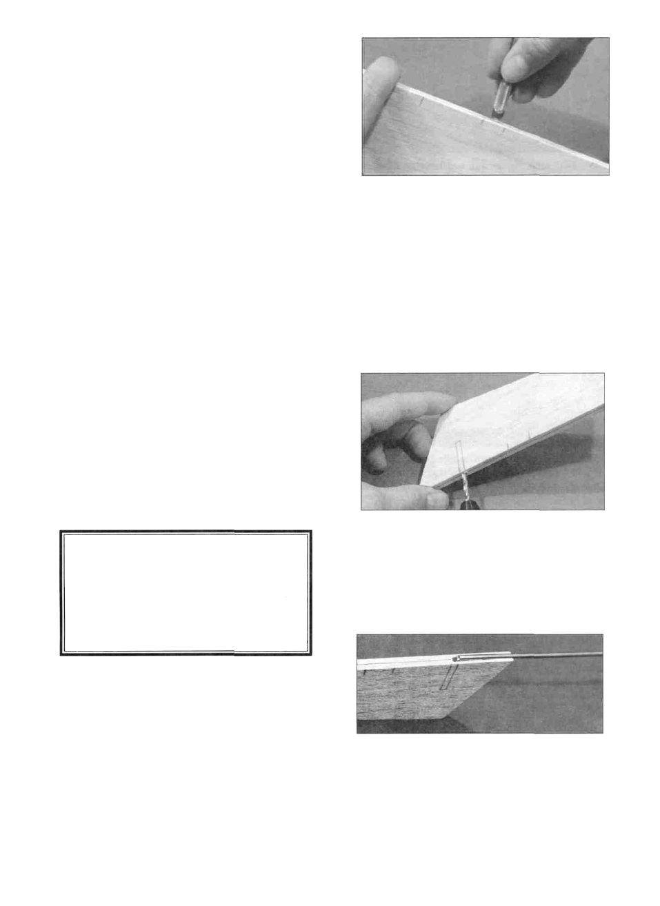
D 3. Check the plans and mark the location of the
torque rods on the rudders and elevators. Drill 7/64"
holes in the rudders and elevators (the holes are drilled
slightly oversize to allow for positioning, and to create a
hard epoxy "sleeve" around the wire). Groove the rudder
and elevator LE to accept the torque rod wires and nylon
bearings (See below).
HINT: Using an X-acto knife, sharpen the inside of one
end of a 1/8" diameter brass tube. and use it to cut the
groove in the leading edge of the rudders and elevators.
9