Great Planes F-14 60 Kit - GPMA0435 User Manual
Page 30
D 2. Punch out the two die-cut 1/8" ply rear servo
trays (F146F32) and test fit your servos to make sure
they fit. You will normally have to enlarge the opening
for the retract servo. Test fit the trays in place. Refer to
the plans to see how they are positioned and sand them if
needed to get them to fit. Tack glue the rear servo trays
in place approx. 1/2" below the lightening hole in the
inner turbine side. Put your servos in place and check to
see that the servo arms are positioned just below the
middle of the lightening hole. Adjust the servo trays if
necessary and securely glue them in place. If you are not
installing retracts, skip ahead to step 10.
so they don't flex during operation. Install an E-Z
connector approximately 9/16" from the center on a large
servo arm. Put the retract servo in place with the servo
arm on it to get an idea where the three pushrods must
meet. Use a 2-56 steel clevis on the retract end of each.
NOTE: There are a couple of places in the construction
sequence where you are required to solder certain metal
parts together. When you find it necessary to solder, use
the following procedure:
A. R o u g h e n the area to be soldered w i t h fine
sandpaper, then thoroughly clean the items to be
soldered with alcohol or degreasing solvent.
B. Assemble the items to be soldered.
C. Apply a small dab of soldering flux.
D. Heat the metal with a soldering gun or iron, and
apply solder to the metal. The metal must get
hot enough to melt the solder, and the solder
must freely flow into the joint.
E. Do not move the parts until the solder has
cooled.
F. Clean off the excess flux with alcohol or solvent.
G. Test the joint by pulling hard.
RETRACT PUSHRODS
D 3. Route the nose retract pushrod first. Try to run
it in a straight line from the servo, through F-2 and along
the fuse side up to the fuel tank floor. The retract
pushrods are not included in the kit. We used a Sullivan
red pushrod outer tube as a guide tube and a steel rod
with yellow pushrod spacers (see step 12 on page 32) on
it for the nose gear. Do not cut the pushrod to length yet.
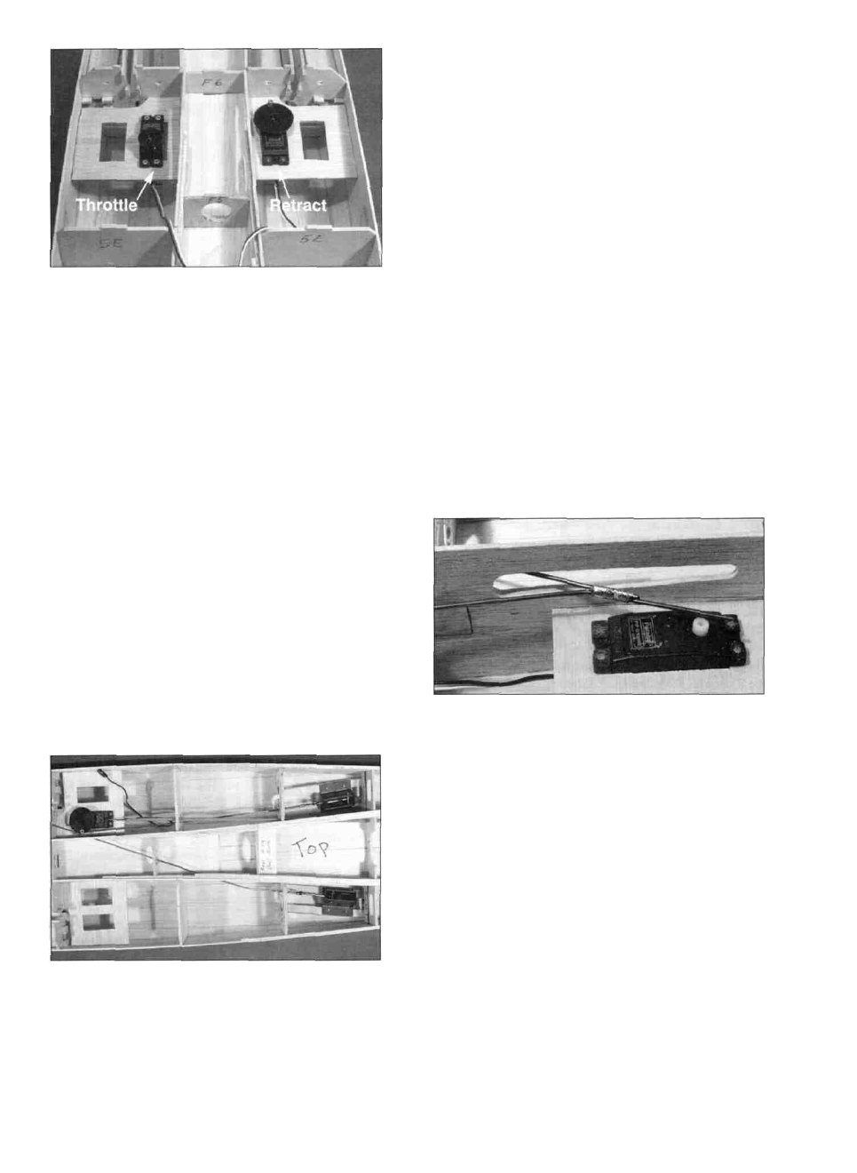
D 4. Route the main gear pushrods as shown in the
photo. Due to the short distance here, we just used steel
pushrod wires without guide tubes. This will work fine
if you keep them running in as straight a line as possible
D 5. The two main gear pushrods need to be joined as
shown in the photo. Bend the two rods so they come
together parallel with each other and cut one off 3/4"
after they join. Wrap the two rods with soft bare copper
wire and actuate the retracts to make sure they both
operate together w i t h o u t the rods binding. When
satisfied with the fit, flow solder into the copper wire to
hold the two together (acid core solder works best for
this). This whole process is a "trial and error" type task
that takes some patience. If the rods get bent more than
necessary during the fitting process, just use them as a
pattern to make new rods with the correct bends. You
want to get this right now because it is tough to correct
after the fuselage is closed up.
D 6. Remove the main gear pushrods and slide a Du-
Bro #103 Strip Aileron Horn and wheel collar onto the
pushrod that runs on the same side as the nose gear rod.
Replace the main gear pushrods and position the aileron
30