Install radio – Great Planes F-14 60 Kit - GPMA0435 User Manual
Page 29
screws, we drilled 1/16" holes. Mount the retract using
the screws you're going to use and then grind off any of
the screws t h a t p r o t r u d e u p i n t o the f u e l tank
compartment. This will keep the screws from damaging
the fuel tank.
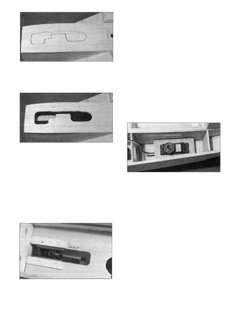
INSTALL RADIO
D 2. Cut the front retract opening pattern out of
the plans and position it on the fuse bottom with the back
edge against the turbine inlets. Trace the opening onto
the fuse bottom.
D 3. Carefully cut the front retract opening into the
fuse. It is a good idea to cut about 1/16" inside the
opening and use a Dremel tool with a sanding drum to
nicely shape the opening to the desired size. NOTE: If
you are using retracts other than Hobbico low profile or
your nose strut is a different length or shape, you will
have to modify the retract opening to fit your nose gear.
D 4. Position the nose retract unit inside the fuse and
line it up with the centerline of the fuse bottom. Move it
forward so the front of the unit is approx. 1/4" behind the
front edge of the retract cutout. Mark where the
mounting holes should be drilled and remove the retract.
D 5. Drill the mounting holes where marked. Since
we mounted our retracts with #2 socket head sheet metal
As discussed on page 5, there are several possible
radio installation options that you can use with the F-14.
The following instructions explain our recommended
radio installation. It requires one rudder servo, two
elevator servos, and one retract servo. If you prefer to
use a different installation, read these instructions but
ignore or modify any steps that do not apply to your
installation.
D 1. Locate one of the die-cut 1/8" ply Front servo
trays (F146F32) and test fit it in place on the right* side
of the fuse. This tray will be for the rudder servo, so test
fit your rudder servo in the opening to make sure it will
fit. Enlarge the opening if necessary. *NOTE: As a
general rule, the rudder servo should go on the same side
as the nose gear retract steering arm. If you are using
fixed gear, install the rudder servo on the left side of
the fuse. The nose gear pushrod w i l l then pass
through the firewall on the opposite side of the
throttle pushrod. Tack glue the servo tray in place
approx. 3/8" below the lightening hole in the inner
turbine side. Put your servo in place and check to see if
the servo arm is positioned correctly in relation to the
lightening hole. The bottom surface of the servo arm
should be slightly above the bottom of the lightening
hole so the nose gear pushrod can go under the front
wing bolt block. Adjust the height of the servo tray if
necessary and securely glue it in place. Mount the
rudder servo using the screws that came with your radio.
If you are only using one elevator servo, install the
remaining front servo tray on the other side of the
fuselage. If you are using two elevator servos, there is
no need to install the other front servo tray.
29