Engine compartment – Great Planes F-14 60 Kit - GPMA0435 User Manual
Page 40
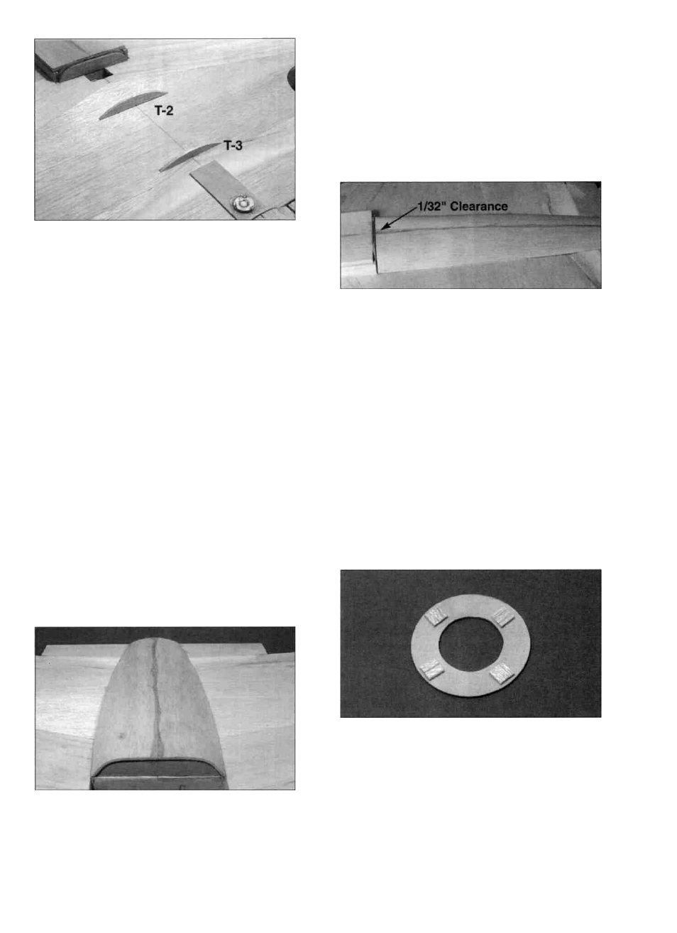
and mark the center of each of these. Glue T-2 and T-3
on the parallel lines you just drew so their center mark is
on the centerline of the wing.
D 4. Test fit the two halves of the die-cut 3/32" balsa
wing turtle deck sheeting (F146F31) together. Sand
them if necessary to achieve a good joint between the
two. Glue them together with thin CA and then sand
both sides smooth. Wet one side of the sheeting with a
damp sponge or paper towel and allow the water to soak
in for 5 minutes or so.
D 5. Remove the wing from the fuse and center the
turtle deck sheeting on T-l and T-4. Carefully bend it
into place to check its fit. It will probably need a little
trimming to make it fit well. First trim it to fit T-l and
T-4 and then check its fit on T-2 and T-3. NOTE: When
fitting the sheeting, trim equally on each side to keep it
symmetrical. This can be tricky to get just right, so don't
get in a hurry, take your time and trim a little at a time.
If you end up with gaps, just fill them with model filler.
Check to make sure you can see the parallel lines you
drew earlier when the sheeting is in place. If not,
lengthen them. The edges of the turtle deck sheeting
should "flow" from the shape of the fuse front into the
shape of the rear fuse top.
D 6. When satisfied with the fit. glue it in place by
first correctly positioning it, then adding thin CA at the
center of T-l and T-4. Allow the glue to cure, then work
it down into place a little at a time on one side and then
the other until it is completely attached to T-l and T-4.
Now poke a few holes with a pin where T-2 and T-3 are
(use the parallel lines as a guide) and apply a couple
drops of thin CA to each hole. Press the sheeting down
against T-2 and T-3 while the glue is curing. Glue the
edges down with thin CA.
D 7. Test fit the wing in place again and trim the
turtle deck sheeting so the w i n g w i l l have enough
clearance to fit on and off easily (approx. 1/32" at both
ends). Don't worry if the turtle deck doesn't match up
perfectly with the fuselage, we will use model filler later
to smooth things out.
ENGINE COMPARTMENT
D 1. Attach the engine mount to F-l, and attach the
engine to the mount. Remove the nose gear from the
engine mount. Mark the outline of the engine mount on
the firewall with a pencil.
D 2. From a scrap of 1/16" balsa, cut four small
pieces and tack glue them to the 1/16" ply spinner ring
(US40F02) as shown, using a very small amount of thick
CA (these will be removed later). IMPORTANT
NOTE: Due to the small engine compartment, shock
absorbing engine mounts that allow the engine to move
are not recommended.
40