Install exhaust nozzles – Great Planes F-14 60 Kit - GPMA0435 User Manual
Page 45
D 3. Drill out the nylon
aileron connectors (NYLON 10)
with a 7/64" drill bit and cut
threads in them using a 6-32 tap.
Screw the connectors onto the aileron torque rods until
the highest holes are approximately 5/8" above the wing
sheeting.
D 4. Screw a nylon clevis
( N Y L O N 1 7 ) onto the two
remaining 12" threaded pushrod wires (WIRES 17)
until the threads are exposed inside the clevis.
INSTALL EXHAUST NOZZLES
D 5. Attach the clevises to the aileron connectors.
Then, with the ailerons in the neutral position, mark the
pushrod wires where they cross the holes in the servo
horn. Remove the pushrods and make a "Z-bend" in the
rods at that point.
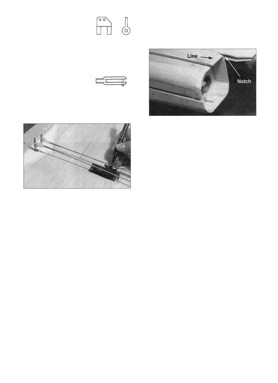
D 1. Use a medium or fine grit sanding block to final
shape the fuselage comers. First sand the turbine sides,
top and bottom to bring the corners flush with the edges.
Then sand the corners so they blend smoothly with the
sides. Now draw a line all around the turbine 3/8"
forward of the back edge of the fuse. Sand the wood
behind this line to taper it a little more than the rest. This
will help you get the exhaust nozzles on.
D 2. Cut a 1/16" wide notch between the fuse
top/bottom and the turbine inner side and top. It should
be about 1/2" deep as shown in the photo at step 1 to
clear the nozzles.
D 6. Remove the servo horn from the servo and work
the Z-bends into the wheel. NOTE: You may have to
enlarge the servo wheel holes with a 5/64" diameter drill
bit. Replace the servo horn and check the operation of
the ailerons. Enlarge the notches in the center wedge
and the TE'S if required to achieve full aileron throw
(See page 55 for the recommended amount of aileron
movement).
D 3. Cut the ABS exhaust nozzles (F146F24) out of
their bases by carefully trimming along the bottom scribe
line. Do not cut the tip off yet. Put a full sheet of fine
grit sandpaper on the work surface and slowly drag the
exhaust nozzles across it to sand the edges smooth. Also
lightly sand the inside of the nozzles where they will
glue to the wood (about 1/2") with fine sandpaper.
D 7. Final sand the entire surface of the wing using a
sanding block with fine sand paper. The LE cross
section at the front of the strakes is shown on the fuse
side view. On the swept back portion of the strakes, the
LE should gradually taper from the sharper cross section
at the front to the normal cross section at rib W5.
NOTE: The strake LE shape is very important, so try to
achieve the shapes shown on the plan.
D 4. Notice that the nozzles have one comer that is
sharper than the other three. This corner goes up and
toward the center of the fuselage. Test fit the exhaust
nozzles in place. Do not force them into place or you
may crack them. They need to slip over the fuselage
approximately 3/8". Sand the fuse if necessary to
achieve a good fit. Test fit both nozzles at the same time
45