Pushrods – Great Planes F-14 60 Kit - GPMA0435 User Manual
Page 31
horn as shown in the next photo. Tighten the set screw
on the horn.
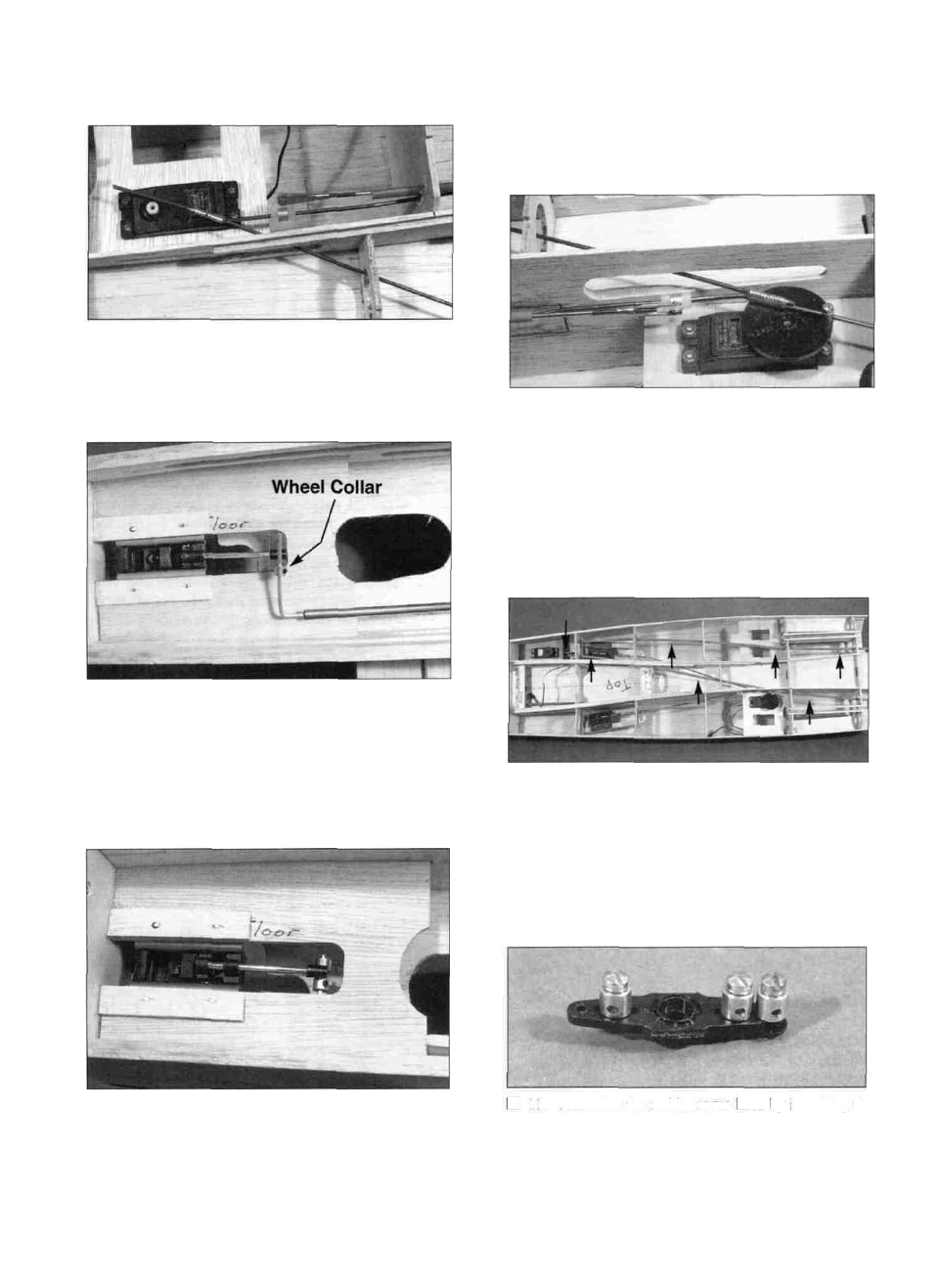
D 7. Pull the nose gear pushrod back and position it
on top of the fuel tank floor. Thread a 2-56 steel clevis
onto the nose gear pushrod and hook it up to the strip
aileron horn. Position the red pushrod outer tube where
you want it and cut it to the correct length.
Pull all three retract pushrods towards the rear of the
plane until both main gear actuating arms are pulled as
far as they will go. Pull the nose gear actuating arm
back. Bend the nose gear wire so it will pass through the
hole in the actuating arm as shown in the photo. Slide a
3/32" wheel collar (not included) onto the nose gear rod.
D 8. Return the nose gear pushrod below the fuel
tank floor and slide it through the actuating arm. Secure
it w i t h a n o t h e r 3/32" wheel collar and check the
operation of all three retracts. The actuating arms of all
three retracts should hit the front and back stops together.
If they don't, adjust the steel clevises and the nylon
aileron horn until they all work together.
D 9. Mount the retract servo using the screws that
came with the radio or servo. Hook the pushrods up to
the retract servo wheel using the E-Z connector and
rotate the wheel by hand (180 degrees) to check the
operation of the pushrods. Make sure they are not
binding.
PUSHRODS
D 10. Route the two- rudder pushrod o u t e r tubes
(PLTB002) as shown in the photo. A long 3/16" drill bit
is very handy here. Drill holes wherever necessary to
run the rods as straight as possible. Cut the excess
tubes off about an inch or so in front of F-7. *If you are
going to operate only one rudder, just run one outer tube
straight back from the servo. (See comments regarding
rudder options on p. 5.)
D 1 1 . Assemble the rudder servo horn by installing the
three EZ connectors as shown in the photo (three parts
31