Landing gear – Great Planes F-14 60 Kit - GPMA0435 User Manual
Page 23
yet! Due to the bending of the turbine side. it is normal
for formers F-2E to slant slightly. This is all right but try
to make both slant the same amount.
FIXED GEAR
D 10. Locate the die-cut 1/8" balsa front turbine
bottoms (F147F11) and rear turbine bottoms
(F146F12) and assemble the turbine bottoms over the
plans. Sand the pieces if needed to achieve a good joint
and glue them together. Test fit the assembled turbine
bottoms in place on the bottom of each turbine. Do not
glue the bottoms in place! Use the bottoms as guides to
align the formers and glue the formers to the sides only.
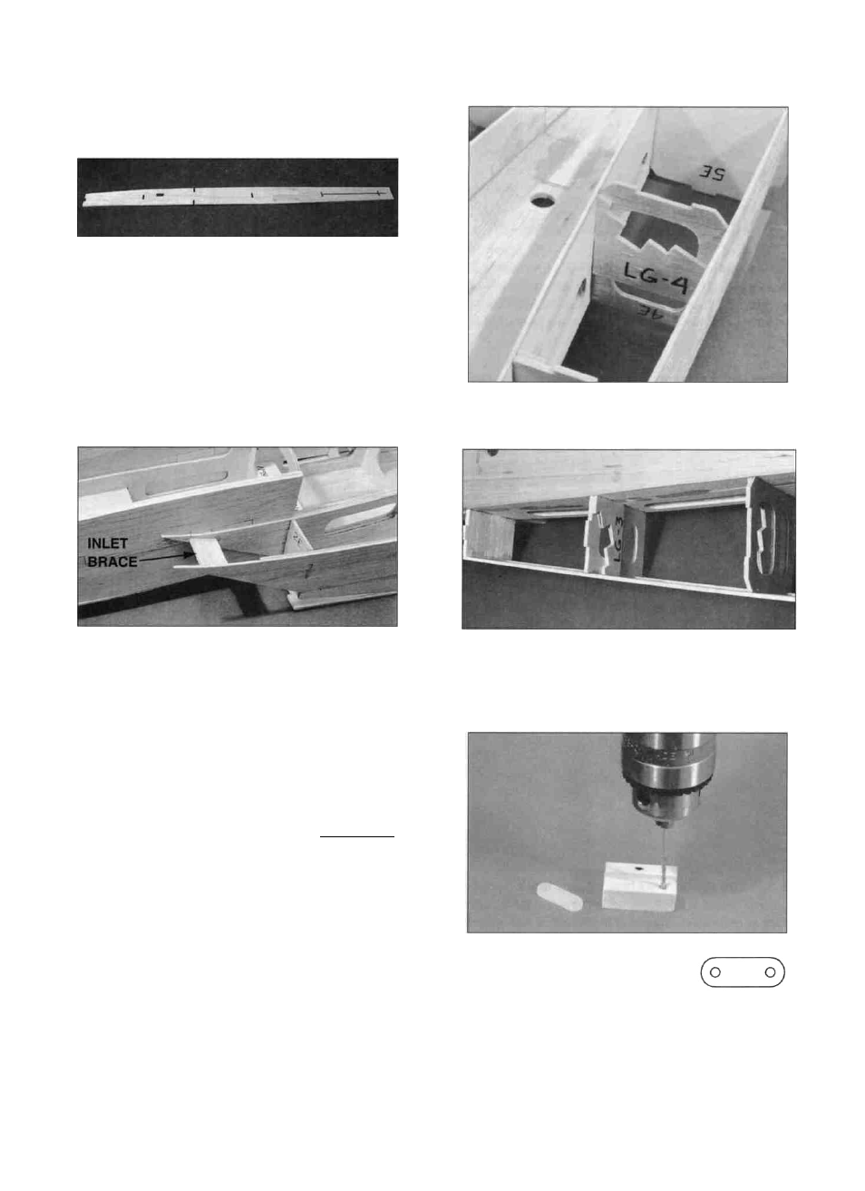
D 1. Test fit the 1/8" ply landing gear doublers LG-3
and LG-4 (F146F32) a g a i n s t formers F-3 and F-4
respectively. They should be positioned as shown in the
D 1 1 . P o s i t i o n the d i e - c u t 1/8" balsa inlet braces
(F146F11) so they hold the t u r b i n e outer sides at a
natural curve, as shown on the plans and glue them in
place. Remove the bottoms after the glue has cured.
D 12. Add 1/2" balsa triangle (WSTR001H) above
and below both 1/4" ply wing bolt blocks and then soak
the fuse sides around both with thin CA to strengthen
this area.
SUGGESTION: From this point on, we recommend
using a padded "cradle" such as a Robart Super Stand to
protect the fuselage from dents and dings. You can
modify the stands to fit the fuselage by c u t t i n g one
upright off flat and enlarging the other upright to fit the
front of the fuselage.
cross section views on the plans. LG-3 on the back of
F-3 and LG-4 on the front of F-4. Sand them if
necessary and then epoxy them in place.
LANDING GEAR
Skip ahead to the "RETRACTS" section if you are
installing retracts.
D 2. Position a nylon landing
gear strap (NYLON36) towards
one end of a 7/16" x 5/8" x 1-1/8"
basswood short grooved LG
block (F146F28) and mark where the holes will be
located. Drill 1/16" holes at these locations. Do this to
both 1-1/8" pieces.
23