Great Planes F-14 60 Kit - GPMA0435 User Manual
Page 32
make up each EZ connector -
EZCONN01. EZCONN02 and
EZCONN03). The two inner
connectors should be the same
distance from the c e n t e r of the horn. The outer
connector is for the nose gear steering pushrod. Make
sure the plastic washers are fully pushed onto the
connector bodies.
halfway through the hole in the nylon swivels using a
4-40 tap. IMPORTANT - We have noticed that the
swivels are sometimes looser than desired if you tap the
threads all the way through the swivel. This looseness is
not very noticeable but can cause control surface flutter
and therefore cannot be permitted. Cut the threads a
little at a time, checking the swivel on the torque rod
each time until it rotates with very little friction. Cut the
excess threads off of the torque rod just past the swivel.
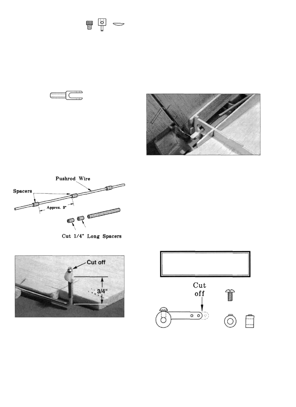
D 12. Screw a nylon swivel clevis (NYLON21) 3/4 of
the way onto the end of t w o 34" pushrod wires
(WIRES 17). Cut 1/4" long spacers from the 6-1/2" piece
of yellow pushrod inner tube (PLTB004) and slide 7
spacers onto each wire approx. 3" apart. Note: If these
spacers do not slide on easily, cut them to a shorter
length. When installing pushrods, position the plastic
spacers so they always stay inside the pushrod guide
tubes. If the spacers are not a tight fit on the pushrod
wires, apply a drop of thin CA to secure each spacer.
D 14. Hook the swivel clevises up to the nylon swivels
on the torque rod. Install the torque rods in the fins and
rudders, slide the rudder pushrod wire into the outer
tubes and insert the fin/rudder assemblies into their slots.
The p u s h r o d wires should pass t h r o u g h the EZ-
connectors and any excess wire should be cut off about
1" past the connector. Check the movement of the
rudders to make sure the clevises don't bind on former
F-7. Trim the holes in F-7 if necessary to allow the
torque rods to move freely. Remove the fins and rudders
but leave the torque rods attached to the swivels. The
torque rods can be rotated and tucked down between the
fin supports.
D 13. Screw a nylon swivel (NYLON20)
onto each of the four small torque rods
( W B N T 1 6 8 ) . NOTE: The t o r q u e rod
swivels m u s t be loose enough to swivel
freely; therefore, we recommend that you cut threads
STEPS 15 AND 16 ARE FOR
FIXED GEAR ONLY!
D 15. Cut 1/4" off the end of the nylon steering arm
(NYLON 16) as shown in the sketch above. Install the
steering arm on the nose gear strut using the 5/32" wheel
collar (WHCL005) and the 6-32 x 1/4" pan head screw
32