Drill engine mount – Great Planes F-14 60 Kit - GPMA0435 User Manual
Page 34
position and mark on the pushrod wires where to cut
them off (approx. 1/16" before the coupler tapers down).
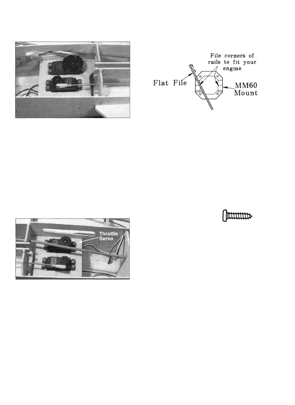
have to file the comers of the engine mount rails to make
room for the crankcase. If the mount would require a
large amount of filing, just replace the mount with one
that correctly fits your engine.
D 21. Remove the elevator pushrods from the fuselage
and cut them oft at the mark. Remove the nylon clevises
from the threaded couplers and solder the couplers to the
wires with acid core solder. After things cool down,
replace the clevises and hook the pushrods up to the
servos. Move each servo arm throughout its range and
check the elevator movement for binding. Adjust the
clevises until the elevators are at neutral when the servo
arms are at neutral. Trim the holes in formers F-6 and
F-7 if necessary to obtain clearance for the elevator
pushrods. Remove the stabs and elevators but leave the
torque rods attached to the swivels. The torque rods can
be rotated and tucked in between the stab supports.
D 1. Place the engine pointing straight ahead on the
mount (in the approximate location shown on the plans)
and mark the mounting hole locations on the mount. At
the marked locations, accurately drill 7/64" (or #36)
holes. NOTE: If you have access to a drill press, use it
for drilling these holes to insure that they are drilled
vertically.
D 2. Now you may use one of the following methods
to attach your engine to the mount:
Method 1: Screw the #6 x 3/4" sheet metal screws
(provided in the kit) through the
engine mounting flange and into
the mount. When first installing
these screws, put a drop of oil
into each screw hole.
Method 2: Cut threads into the holes you just drilled
using a 6-32 tap and tap wrench. If you use this method,
you'll have to supply your own bolts (6-32 x 1" socket
head cap screws) for attaching the engine to the mount.
D 22. I n s t a l l the t h r o t t l e servo u s i n g the screws
provided with your radio. It should be installed in the
remaining rear servo tray opening to help balance the
airplane.
D 3. Attach the engine mount to the firewall using the
6-32 x 5/8" cap screws.
DRILL ENGINE MOUNT
(Great Planes MM60D90 or similar glass-filled nylon
mount)
NOTE: If the engine mount supplied in the kit does not
appear to fit your engine (example: OS .61 SF), you may
D 4. Screw your engine to the mount, and determine
the location where the throttle pushrod w i l l pass
through F-1. Due to the length of the throttle pushrod, a
flexible plastic pushrod (not included) works well for
this. Drill a 3/16" hole (or whatever size you need) in
the firewall for the throttle pushrod guide tube. The hole
should be 1/4" away from the outside of the fuselage to
34