Great Planes F-14 60 Kit - GPMA0435 User Manual
Page 13
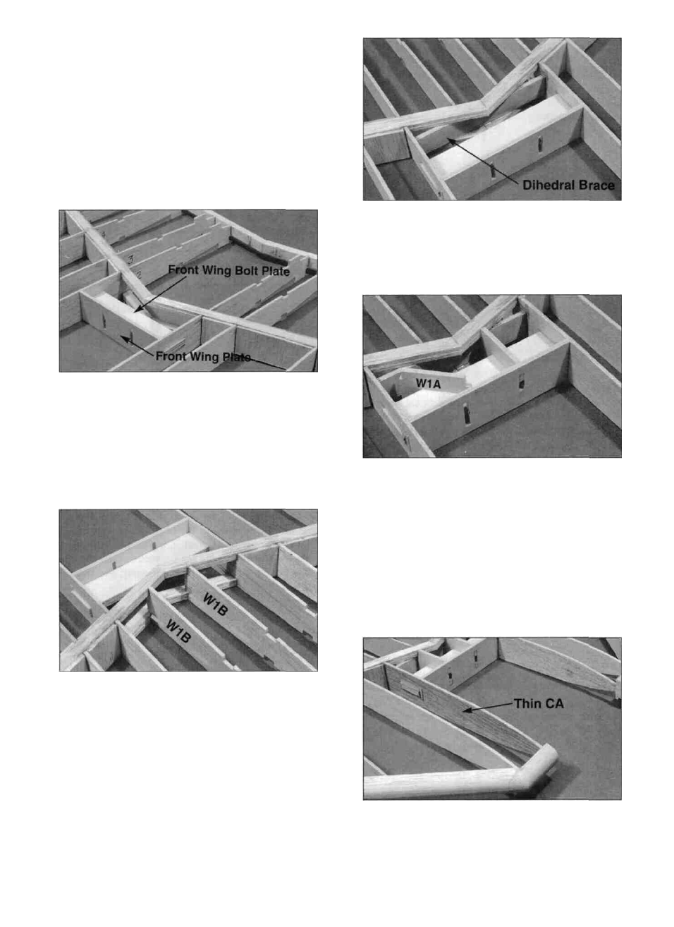
bolt plate (F146W18) to check the spacing. Make sure
both panels are on a flat surface and lined up correctly
with the jig tabs against the work surface. Refer to the
plans and the following photo. NOTE: The notches for
the middle spar should form a straight line when the
proper amount of sweep is achieved.
D 2. When satisfied with the fit of the two panels,
insert the front wing bolt plate along with the wing front
plate into the slots in the W-2 ribs and glue the spars and
TE'S together with epoxy. Also glue the plates in place.
D 4. Securely glue the 1/8" x 23/32" x 4-5/32" ply
dihedral brace (F146W12) in place between the spars
and against the W1B ribs with epoxy.
D 3. Install the d i e - c u t 1/8" balsa W 1 B ribs
(F146W01) by inserting them into the trailing edge slots
and rotating them u n t i l the front notches contact the
spars. Make sure the aileron servo rail slots in the ribs
are positioned down (near the work surface) and glue
them in place.
D 5. Slide the die-cut 1/8" ply W1A ribs (F146F32)
into place by positioning them at an angle as shown on
the left side of the photo and rotating them until they fit
into place as shown on the right side of the photo. Be
careful not to push the wing front plate out away from
the wing bolt plate during this step. Sand the inside slot
of the W1A ribs if they are hard to slide over the wing
bolt plate. Glue all these pieces together with thin CA
followed by either epoxy or thick CA.
D 6. Soak the entire outer side of each W2 rib with
13