Great Planes F-14 60 Kit - GPMA0435 User Manual
Page 41
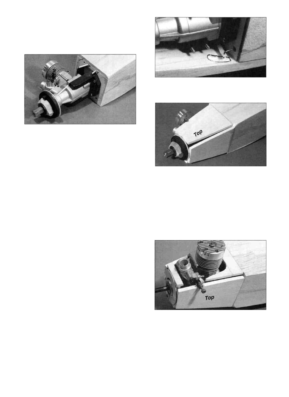
D 3. Now center your 2-1/4" diameter spinner
backplate (HCAQ3750 recommended) over the spinner
ring, and tack glue it to the 1/16" spacers.
D 4. S l i d e the s p i n n e r r i n g / s p i n n e r backplate
assembly onto the drive shaft and temporarily hold it in
place with the prop and prop nut. (Photo shows only the
hub of an old prop).
D 5. Locate the three identical 1/4" shaped balsa
cowl pieces (F146F29) in the kit. With the fuselage
upside down, trial fit one of the pieces in place on the
bottom of the engine compartment. Study the plan to see
the correct positioning of this part. The cowl pieces
should be centered in relation to the side they are
installed on. Note how the front of the cowl piece meets
the spinner ring. By trial and error, sand a little at a time
off the front and rear of the bottom cowl piece until it
mates at the proper angle with the firewall and the back
of the spinner ring. Now glue the cowl piece to the
firewall and the spinner ring.
nose gear pushrod in the cowl piece. Now remove the
nose gear parts.
D 8. Custom f i t another cowl piece for the top of the
nose between the firewall and the spinner ring, trimming
as necessary for needle valve clearance. Also fit the
remaining cowl piece to the side of the nose. When
satisfied with the fit of these two pieces, glue them in
place. NOTE: The corner gaps are intended to be there.
Later, they will help gauge when the nose has been
sanded enough.
NOTE: If you have installed a retractable
nose gear, skip steps 6 and 7.
D 6. Turn the fuselage right side up and use a long
5/32" drill bit (or a sharpened piece of 5/32" O.D. brass
tube) to drill a hole in the bottom cowl piece for the nose
gear strut. Insert the drill through the holes in the engine
mount and drill down through the bottom cowl piece.
D 7. Temporarily install the nose gear, steering arm
and nose gear pushrod wire. Notice that the steering arm
and the pushrod wire will bind against the cowl piece,
especially in a turn. Carve out a clearance slot for the
D 9. Use scraps of 1/4" wood (from the t u r b i n e
corners) to fill in around the engine side of the nose.
SUGGESTION: The temptation is to close up this area
too much! We recommend that you leave large enough
openings to allow you to easily remove the engine and
mount and also have convenient access to the throttle
linkage.
41