Great Planes F-14 60 Kit - GPMA0435 User Manual
Page 11
other semi-soft (and flat) surface, into which you may
easily stick pins to f i r m l y hold down the wing parts
while building, to avoid warps. *Available from lumber
companies and home centers.
NOTE: You should also be aware of the following:
This wing is constructed with 1-3/4 degrees of washout
(TE higher than LE at the wing tip) built-in. When the
wing is upright, the tabs on the rear portion of the ribs set
the ribs at the proper angles to achieve this slight twist.
When you flip the wing over to work on the bottom side,
the jig tabs on the top of the wing will hold the correct
washout in the wing.
D D 1. Cut the Wing Plan apart on the heavy dashed
line. Tape the right (or left) wing panel plan to your flat
work surface, and cover the wing drawing with waxed
paper (so you won't glue the wing to the plan!).
D D 2. Carefully punch out all the die-cut 3/32" and
1/8" balsa wing ribs. Sand the edges slightly to remove
any die-cutting irregularities or "fuzz."
with the rear-most jig tab against the work surface.
Use a 90-degree triangle to keep the ribs vertical.
D D 5. The shaped and notched wing trailing edges
(F146W07) are fastened together by a thin strip of balsa.
Separate them by cutting with an X-acto knife. Position
the TE in place by working the rear ends of the ribs into
the notches in the TE. Center the TE vertically on each
rib and glue it in place with thin CA.
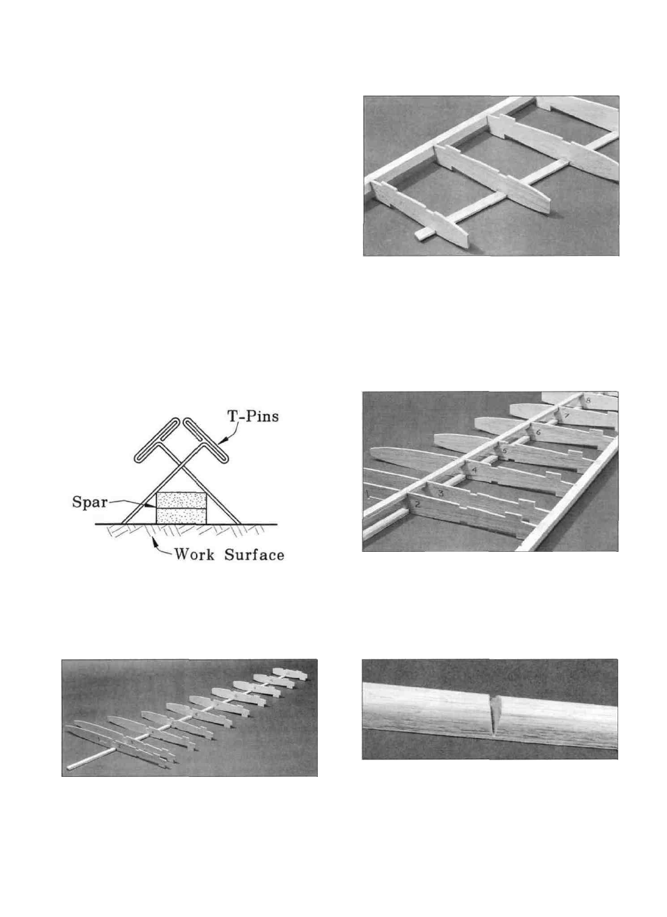
D D 3. Cross-pin one of the spars to the plan with the
long spar down. and with the thick end (2 laminations)
toward the root. The tapered end of the spar doubler
should end just inside (1/4") of rib W8.
D D 6. Glue the top spar in place (with the long spar
on top). Make sure it is fully seated in the notches so it
does not s t i c k above t h e top s u r f a c e of the ribs.
Remember, the spar doubler stops just inside rib W8.
D D 4. Glue ribs W2 through W11 onto the spar in
their correct position. Notice that the ribs are installed
D D 7. Position a shaped b a l s a Leading Edge
(F146W06) over the Leading Edge Template on the wing
plan and mark where the notch goes. Use a razor saw to
11