3 specifications – Flintec FT-10xx User Manual
Page 8
FT-10 Smart Process Indicator, Technical Manual, Rev. 1.0, January 2014
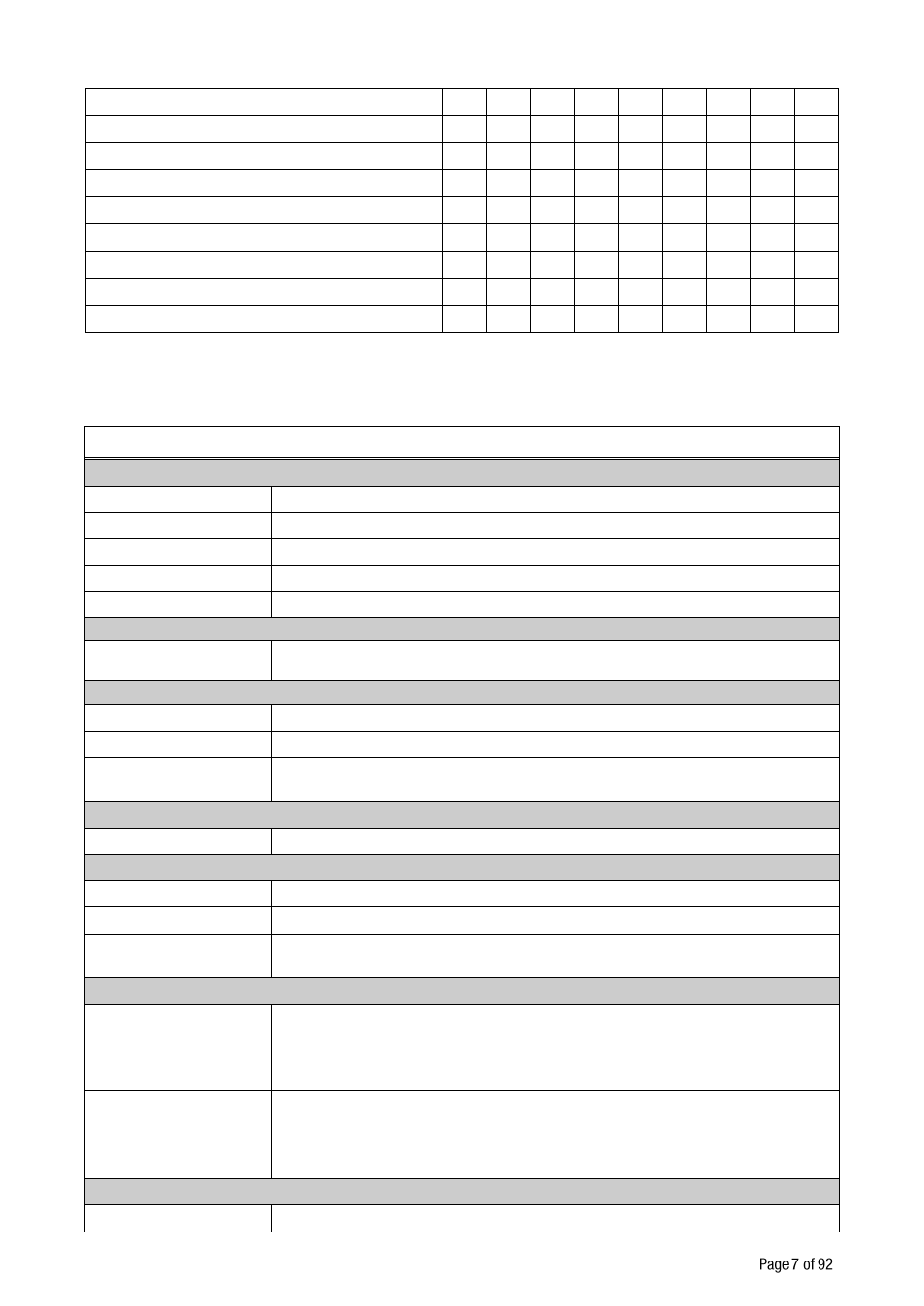
3.3 Specifications:
Common Specifications
A/D Converter
A/D converter type
24 bit Delta-Sigma radiometric with integral analog and digital filters
Conversion rate
Up to 1600 measurement values per second
Input sensitivity
0.1 μV/d (non approved)
Analog input range
0 mV to +18 mV ( unipolar ) ;
- 18 mV to +18 mV ( bipolar )
Internal resolution
up to 16 000 000
External Resolution
Display resolution
up to 999 999 increment
Scale Calibration and Functions
Calibration
Calibration is performed with or without test weights ( eCal )
Digital filter
10 steps programmable adaptive filter
Weighing functions
Taring, zeroing, auto zero tracking, motion detection, auto zero at power up, net
indication at power on, increased resolution
Linearity
Within 0.0015% FS,
2 ppm/°C
Load cells
Excitation
5 VDC max. 300 mA
Number of load cells
Up to 8 load cells 350 Ω or 18 load cells 1100 Ω in parallel
Connection
4- or 6-wire technique.
Cable length: maximum 250 m/mm² for 6-wire connection
Digital Inputs and Outputs
Digital Inputs
2 optoisolated digital inputs at FT-10 AN,
4 optoisolated digital inputs at FT-10, FT-10 MB, FT-10 PB, FT-10 PN, FT-10
EN, FT-10 CO;
12 to 28 VDC, 10mA
Digital Outputs
4 free relay contact at FT-10 AN,
5 free relay contact at FT-10, FT-10 MB, FT-10 PB, FT-10 PN, FT-10 EN, FT-10
CO
250 VAC or 30 VDC , 1A
Power consumption
12 to 28 VDC max. 300 mA
Electronic calibration (eCal) over field bus
-
-
-
X
X
X
X
X
X
Zero and Span calibrations over field bus
-
-
-
X
X
X
X
X
X
Zero adjustment
X
X
X
X
X
X
X
X
X
Span adjustment with test weights
X
X
X
X
X
X
X
X
X
Span adjustment for filled tanks
X
X
X
X
X
X
X
X
X
3 point calibration ( linearity correction )
X
X
X
X
X
X
X
X
X
Programming by IndFace PC software
X
X
X
X
X
X
X
X
X
8 load cells 350 Ω or 18 load cells 1100 Ω
X
X
X
X
X
X
X
X
X
12 to 28 VDC power supply range
X
X
X
X
X
X
X
X
X