10 digital inputs and outputs connection – Flintec FT-10xx User Manual
Page 20
FT-10 Smart Process Indicator, Technical Manual, Rev. 1.0, January 2014
4.3.10 Digital Inputs and Outputs Connection
Digital Inputs:
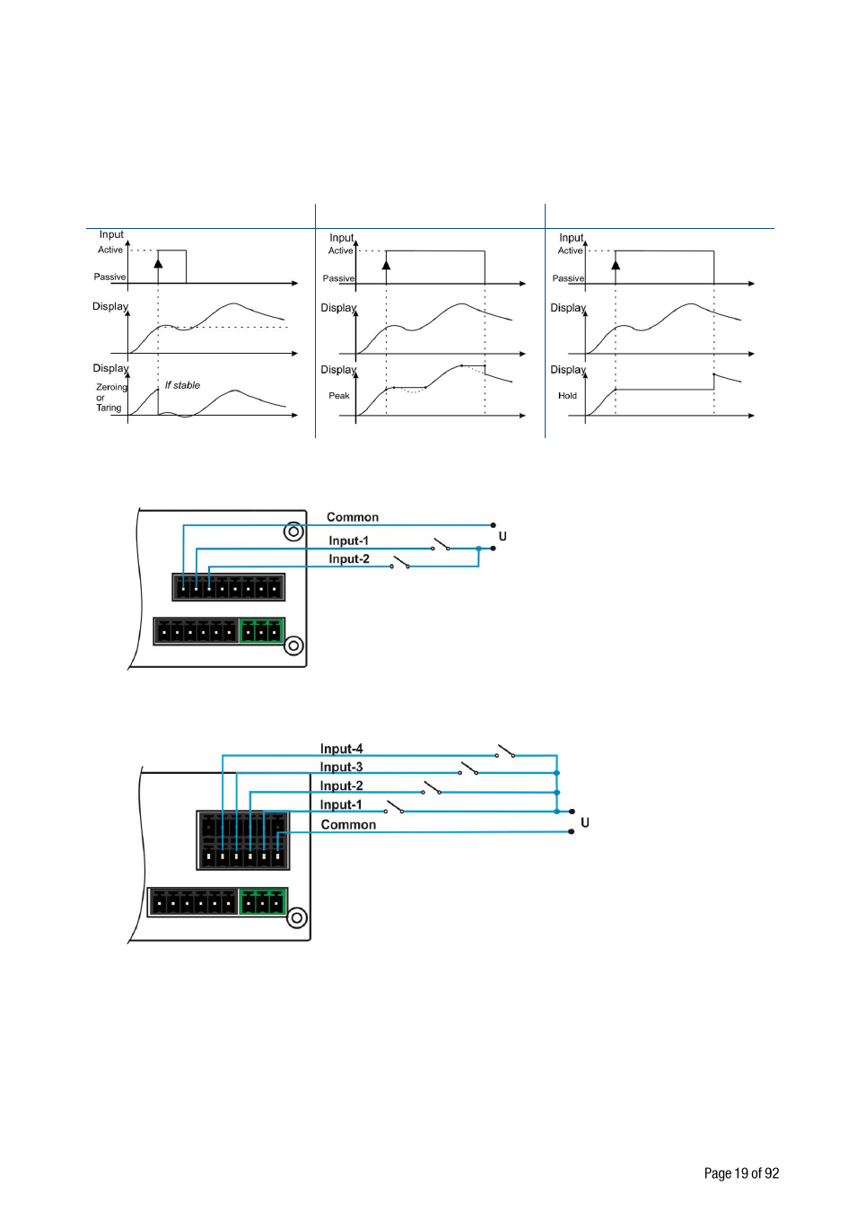
FT-10 inputs are independently programmable for zeroing, taring, clear, print, key lock, peak, hold, and as a
fieldbus input port. If the input is programmed as a fieldbus input port, the input status is transferred to the
PLC by fieldbus command. Inputs are 12 .. 28 VDC, 10 mA.
Inputs connection diagram is shown in Figure 4.14.
FT-10 AN
FT-10,
FT-10 MB,
FT-10 PB,
FT-10 PN,
FT-10 EN,
FT-10 CO
Figure 4.15 - FT-10 Inputs connection diagram
Digital Outputs:
FT-10 instruments digital outputs are can be used as a standard, threshold and window. Threshold and
window outputs are also programmable positive or negative polarity. Digital outputs of FT-10 are also
programmable as a fieldbus port to control them with a fieldbus commands. Refer to parameter [ 130 ] on
Page 29 and [ 70- ] on Page 36 . Outputs are 250 VAC or 30 VDC, 1A.
Outputs connection diagram is shown in Figure 4.16
Zero or Tare functions :
Peak function :
Hold function :