E 48, Ft-10, 1 modbus rtu data structure – Flintec FT-10xx User Manual
Page 49: Odbus, Only, ] rs 232c serial port
FT-10 Smart Process Indicator, Technical Manual, Rev. 1.0, January 2014
8. M
ODBUS
RTU
(
ONLY
FT-10
MB
)
FT-10 MB indicator has a Modbus RTU interface over RS 485 / RS 232C serial port. This interface can be
programmable to High-Low or Low-
High for different type of PLC’s. You can find below the difference of
these data formats and some companies using these formats. Two types are available as;
8.1 Modbus RTU Data Structure
After programming RS 485 / RS 232C serial port for Modbus RTU, it can be used as a Modbus RTU slave on
Modbus RTU network. The Modbus slave address is defined in the RS-485 address (Page 25). Functions
code ‘0x03’ (Read Holding Registers) and ‘0x10’ (Preset Multiple Registers) are supported.
Modbus RTU High-Low: In two word registers, the data is stored to the registers in big-endian format. Least
significant word is stored to the highest register address; and most significant word is stored to the lowest
register address.
Modbus RTU Low-High: In two word registers, the data is stored to the registers in little-endian format.
Least significant word is stored to the lowest register address; and most significant word is stored to the
highest register address.
[00-] RS 232C Serial Port
This sub-block includes the parameters about the 1
st
serial interface of FT-10.
[000 3 ] Data Format
4 : Modbus RTU High-Low
5 : Modbus RTU Low-High
Set the RS 485 / RS 232C Data Format : Modbus
RTU
High-Low
or
Modbus
RTU
Low-High
RS-485 Data Length & Parity
: 8 none 1,
RS-485 Address
: 01 to 31
Make the RS-485 / RS 232C parameter settings as defined on (Page 24).
Please find Modbus information in the web site of
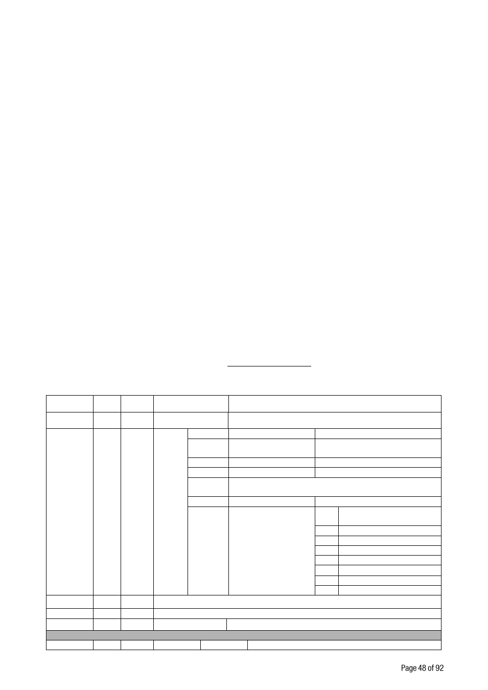
Modbus RTU Command Table;
Address
R/W
Word
Command
Definition
40001
R
2
Indicated weight
( Net if the indication is in Net )
40003
R
1
Status
D0
0
– System Ready
1
– System Busy
D1
0
– Error ( D13-D15
)
1
– Data ok
D2
0
– Weight Stable
1
– Weight unstable
D3
0
– Gross Mode
1
– Net mode
D4
–
D11
Not used
D12
0
– Out of zero range 1 – Weight is in zero range
D13
D14
D15
Error Code
De
c
Description
0
No Errors
1
ADC out of range
2
ADC over range
3
ADC under range
4
System error
5
In programming mode
6
Low/High voltage det.
40004
R
2
Tare weight
40006
R
2
Gross weight
40008
R
1
Status
Motion, Net mode, Data ok, (image of register 40003)
40009
R/W
1
Control
Dec
Description