2 gsdml configuration, 3 profinet data structure – Flintec FT-10xx User Manual
Page 61
FT-10 Smart Process Indicator, Technical Manual, Rev. 1.0, January 2014
10.2 GSDML Configuration
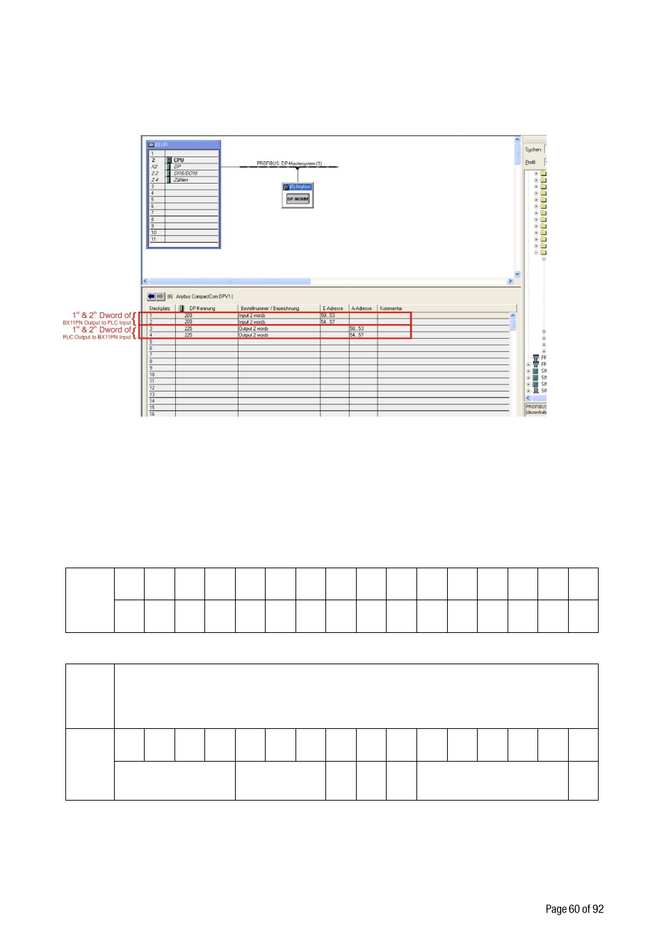
Profinet data structures of FT-10 PN includes 2 x Input 2 words and 2 x Output 2 words. GSDML
configuration for PLC programmers is shown in Figure 10.1.
Figure 10.1 - GSDML Configuration
10.3 Profinet Data Structure
FT-10 PN Output to PLC Input
Bitwise of a Dword:
Dword
(Only
read)
D31 D30 D29 D28 D27 D26 D25 D24 D23 D22 D21 D20 D19 D18 D17 D16
D15 D14 D13 D12 D11 D10 D9
D8
D7
D6
D5
D4
D3
D2
D1
D0
1
st
Dword
By default, Indicated weight value is represented.
To represent other weight or calibration status, refer to next Dword.
2
nd
Dword
Out
5
Out
4
Out
3
Out
2
Out
1
In
4
In
3
In
2
In
1
Error codes of FT-10
PN
Not in use
Zero
range
Gros
s
Net
MD Read command response
Cmd
Flg
FT-10 PN Output to PLC Input 2
nd
Dword