2 canopen data structure – Flintec FT-10xx User Manual
Page 74
FT-10 Smart Process Indicator, Technical Manual, Rev. 1.0, January 2014
Page 73 of 82
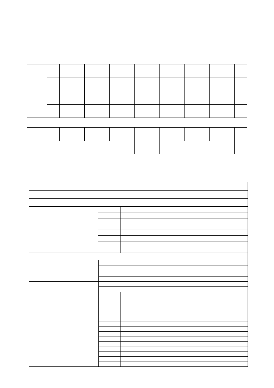
12.2 CANopen Data Structure
FT-10 CO Output to PLC Input
Bitwise of a Ulong:
Unsigned
Long
(Only
read)
D63 D62 D61 D60 D59 D58 D57 D56 D55 D54 D53 D52 D51 D50 D49 D48
D47 D46 D45 D44 D43 D42 D41 D40 D39 D38 D37 D36 D35 D34 D33 D32
D31 D30 D29 D28 D27 D26 D25 D24 D23 D22 D21 D20 D19 D18 D17 D16
D15 D14 D13 D12 D11 D10 D9
D8
D7
D6
D5
D4
D3
D2
D1
D0
TxPDO 1
(T_UL1)
Out
5
Out
4
Out
3
Out
2
Out
1
In
4
In
3
In
2
In
1
Error codes of FT-10 CO
Not in use
Zero
range
Gross
Net
MD
Read command response
Cmd
Flg
By default, Indicated weight value is represented.
To represent other weight or calibration status, refer to D33…D37.
FT-10 CO Output to PLC Input TxPDO 1 (T_UL1)
Bit Number
TxPDO 1 (T_UL1) Description
D63 … D56
Outputs
Output bit status ( Active = 1 )
D55 … D48
Inputs
Input bit status ( Active = 1 )
D47 … D44
Error Codes of
FT-10 CO
Bin
Dec
0000
0
No error found
0001
1
ADC out
0010
2
ADC over
0011
3
ADC under
0100
4
System Error
0101
5
In programming mode
0110
6
Low/High Voltage Error
D43 … D41
Not in use
D40
Zero Range
0
Weight is in zero range
1
Weight is out of zero range
D39
Indication
0
Gross
1
Net
D38
MD
– Motion
Detection
0
Stable
1
Dynamic
D37 … D33
D37 … D33
Read
Command
Response
Read
Command
Response
00000
0
Indicated weight
00001
1
Gross weight
00010
2
Tare weight
00011
3
Calibration Status (Refer to Table 12.1)
00100
01110
4
14
Not used
01111
15
Set Point-1 Low
10000
16
Set Point-1 High
10001
17
Set Point-2 Low
10010
18
Set Point-2 High
10011
19
Set Point-3 Low
10100
20
Set Point-3 High
10101
21
Set Point-4 Low
10110
22
Set Point-4 High
10111
23
Set Point-5 Low