2 digital output functions [70 – Flintec FT-10xx User Manual
Page 37
FT-10 Smart Process Indicator, Technical Manual, Rev. 1.0, January 2014
5.5.2 Digital Output Functions [70-]
In this block, the digital outputs are programmed for the functions indicated in the table below.
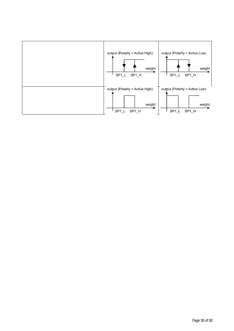
Threshold Output :
2 set point values are entered. SP1
is the point that the output goes
active when the weight increased
from SP1_H. SP1_L is the point that
the output drops to passive state
when the weight decreased to
SP1_L.
Inverse function is available.
Window Output:
2 set point values are entered. The
output is active when the weight is
between SP1_L and SP1_H. Inverse
function is available.
Table 5.1 - Digital output functions
[700 0] Output 1
Refer to Table 5.1 to select the output function.
0 : No function on output 1
1 : Threshold (Active High)
2 : Threshold (Active Low)
3 : Window (Active High)
4 : Window (Active Low)
5 : Fieldbus output
[701 0] Output 2
Refer to Table 5.1 to select the output function.
0 : No function on output 2
1 : Threshold (Active High)
2 : Threshold (Active Low)
3 : Window (Active High)
4 : Window (Active Low)
5 : Fieldbus output
[702 0] Output 3
Refer to Table 5.1 to select the output function.
0 : No function on output 3
1 : Threshold (Active High)
2 : Threshold (Active Low)
3 : Window (Active High)
4 : Window (Active Low)
5 : Fieldbus output
[703 0] Output 4
Refer to Table 5.1 to select the output function.
0 : No function on output 4
1 : Threshold (Active High)
2 : Threshold (Active Low)
3 : Window (Active High)
4 : Window (Active Low)
5 : Fieldbus output