E 39, 1 continuous data output, Erial – Flintec FT-10xx User Manual
Page 40: Utputs
FT-10 Smart Process Indicator, Technical Manual, Rev. 1.0, January 2014
6. S
ERIAL
D
ATA
O
UTPUTS
FT-10 indicator family has different kind of serial interfaces like RS 232, RS 485 and Ethernet etc. In this
section, you will find the data structure of different type of the data outputs via these serial ports except field
bus interfaces. You will find detailed information on field bus interfacing in the related sections.
6.1 Continuous Data Output
Continuous data output of the instrument is transmitted in the following data structure. The serial ports of
FT-10 are suitable for bi-directional communication. If you transmit ASCII codes of P(print), Z(zero), T(tare)
or C(clear) letters to the serial port of FT-10; the indicator will act like the related keys are pressed.
CR (Carriage return) and LF (Line feed) codes can be enabled or disabled from response but they must be
sent to end of ASCII command.
CHK (Checksum) can be enabled or disabled from both command and response and only continuous data
output can be programmed for more than one interface.
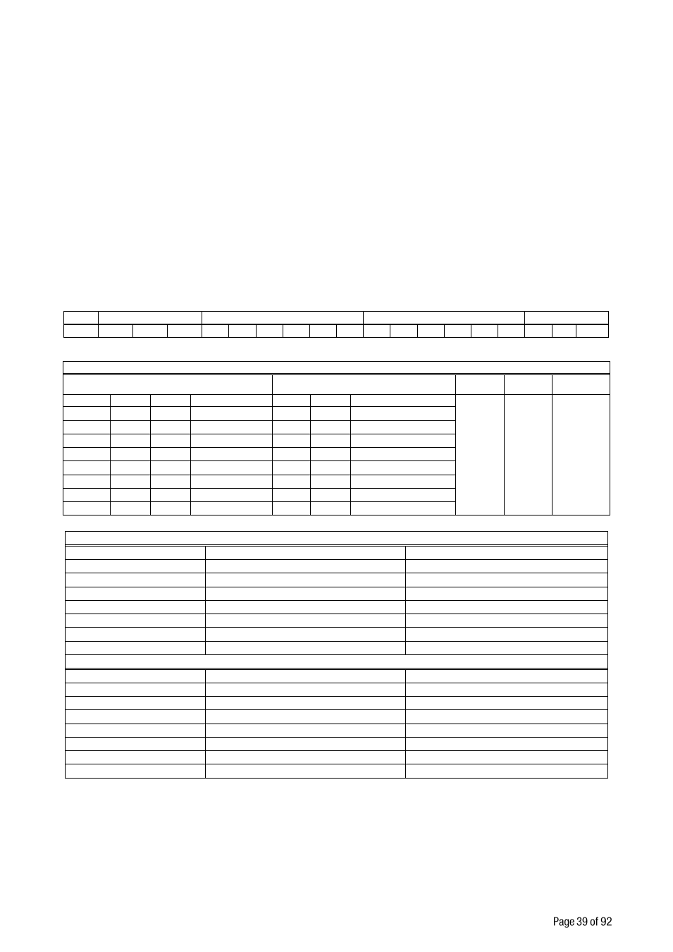
The data format of continuous data output is;
Status
Indicated
Tare
STX
STA
STB
STC
D5
D4
D3
D2
D1
D0
D5
D4
D3
D2
D1
D0
CR
LF CHK
The including of the status bytes STA, STB and STC are:
Definition Table for Status A ( STA )
Bits 0, 1 and 2
Bits 3 and 4
Bit 5
Bit 6
Bit 7
0
1
2
Decimal point
3
4
Increment size
Al
way
s
1
Al
way
s
1
X
0
0
0
XXXXOO
1
0
X 1
1
0
0
XXXXXO
0
1
X 2
0
1
0
XXXXXX
1
1
X 5
1
1
0
XXXXX.X
0
0
1
XXXX.XX
1
0
1
XXX.XXX
0
1
1
XX.XXXX
1
1
1
X.XXXXX
Definition Table for Status B ( STB )
Bit 0
0 = Gross
1 = Net
Bit 1
0 = Weight positive
1 = Weight negative
Bit 2
0 = No Error
1 = Error
Bit 3
0 = Stable
1 = Unstable
Bit 4
Always = 1
Bit 5
Always = 1
Bit 6
0 = Not power on zeroed
1 = Zeroed with power on zero
Bit 7
x
Definition Table for Status C ( STC )
Bit 0
Always 0
Bit 1
Always 0
Bit 2
Always 0
Bit 3
Always 0
Bit 4
Always 1
Bit 5
Always 1
Bit 6
Always 0
Bit 7
x
CHK (Checksum) = 0
– ( STX
STATUS A
.....
LF )
Error Messages: UNDER, OVER, A.OUT, L-VOLT, H-VOLT, are represented in Indicated data fields.
Note:
The weight data is represented with right aligned and the error messages are represented with left
aligned.
Note:
The continuous data is started to send after 20 seconds after power-on. This property helps to
connect IndFace1X on RS 485 bus.