Flintec FT-10xx User Manual
Page 64
FT-10 Smart Process Indicator, Technical Manual, Rev. 1.0, January 2014
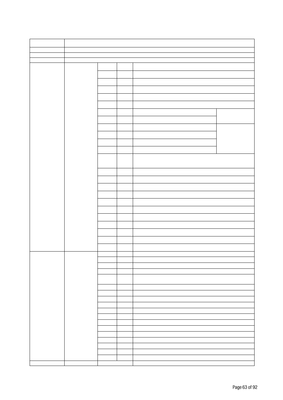
PLC Output to FT-10 PN Input 2
nd
Dword
Bit Number
2
rd
Dword descriptions
D31 … D24
Set / Reset digital outputs
D23 … D16
Expanded Commands List ( Refer to Table 10.2)
D15 … D11
Not in use
D10 … D6
D10 … D6
Command List
(continuation
of previous
page)
Bin
Dec
Commands
00000
0
None command is activated
00001
1
Zero
00010
2
Tare
00011
3
Clear
00100
4
00101
5
Adjust zero calibration
Calibration
00110
6
Adjust span calibration
(1)
00111
7
Total Load Cell Capacity
(1)
eCal
Coefficients
Refer to par.
[313]
01000
8
Average mV/V value
(1)
01001
9
Dead Load value
(1)
01010
10
Save the coefficients of eCal
01011
01110
11
14
Not used
01111
15
Set Point-1 Low
(1)
10000
16
Set Point-1 High
(1)
10001
17
Set Point-2 Low
(1)
10010
18
Set Point-2 High
(1)
10011
19
Set Point-3 Low
(1)
10100
20
Set Point-3 High
(1)
10101
21
Set Point-4 Low
(1)
10110
22
Set Point-4 High
(1)
10111
23
Set Point-5 Low
(1)
11000
24
Set Point-5 High
(1)
11111
31
Use the Expanded Command list ( Refer to Table 10.2)
D5 ... D1
Read Data
Selection
00000
0
Indicated weight
00001
1
Gross weight
00010
2
Tare weight
00011
3
Calibration Status ( Refer to Table 10.1)
00100
01110
4
14
Not used
01111
15
Set Point-1 Low
( 2 )
10000
16
Set Point-1 High
10001
17
Set Point-2 Low
( 2 )
10010
18
Set Point-2 High
10011
19
Set Point-3 Low
( 2 )
10100
20
Set Point-3 High
10101
21
Set Point-4 Low
( 2 )
10110
22
Set Point-4 High
10101
21
Set Point-4 Low
( 2 )
10110
22
Set Point-4 High
10111
23
Set Point-5 Low
( 2 )
11000
24
Set Point-5 High
11111
31
Use the Expanded Command list ( Refer to Table 10.2)
D0
New CMD
Toggle
Apply commands which are listed in this table
(1) Write this command after writing values to 1
st
Dword, then apply this command with New CMD
(2) Only set point low addresses are used if the set point is programmed as standard.