3 rs 232c connection, 4 rs 485 and modbus-rtu connection, Warning – Flintec FT-10xx User Manual
Page 15
FT-10 Smart Process Indicator, Technical Manual, Rev. 1.0, January 2014
Junction box
6 Wire-cable
FT-10 Indicator
Bridges
4W-Load cell
Shield
Shield
+ Exc
+ Sig
- Sig
- Exc
Shield
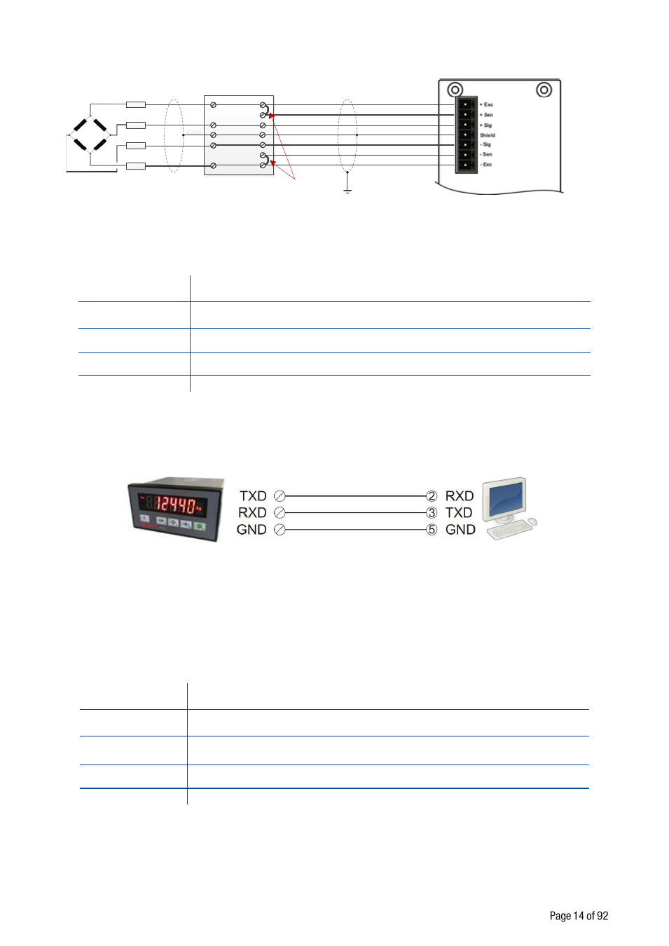
4.3.3 RS 232C Connection
RS 232C port usage and specifications are shown in the table 4.1
Usage
Interfacing with PC or PLC, remote display connection,
programming via IndFace1X
Data formats
Continuous, Fast Continuous, Printer Format, BSI Protocol,
Modbus-RTU High-Low, Modbus-RTU Low-High
Baud rate
1200 / 2400 / 4800 / 9600 (Default) / 19200 / 38400 / 57600 / 115200 bps
Length and parity
8 bit no parity (Default), 7 bit odd, 7 bit even
Start / Stop bits
1 start bit and 1 stop bit
Table 4.1
– RS 232C Serial Interface Specifications
RS 232C serial connection is done with three wire as indicated below.
Figure 4.3 - RS 232C serial interface connections
Warning:
Connecting the shield to the reference ground will protect your weighing system against EMC
disturbances.
4.3.4 RS 485 and Modbus-RTU Connection
RS 485 port usage and specifications are shown in the table below ( Page 25 ).
Usage
Interfacing with PC or PLC, remote display,
programming via IndFace1X,
Data formats
Continuous, Fast Continuous, Printer Format, BSI Protocol,
Modbus-RTU High-Low, Modbus-RTU Low-High
Baud rate
1200 / 2400 / 4800 / 9600 (Default) / 19200 / 38400 / 57600 / 115200 bps
Length and parity
8 bit no parity (Default), 7 bit odd, 7 bit even
Start / Stop bits
1 start bit and 1 stop bit
Table 4.2 - RS 485 Serial Interface Specifications
RS 485 serial connection is done with three wire as indicated in Figure 4.4. Line termination resistors ( 110
ohm ) are needed both ends of the RS 485 line.