Flintec FT-10xx User Manual
Page 45
FT-10 Smart Process Indicator, Technical Manual, Rev. 1.0, January 2014
U
Read digital inputs
Command :
[ADR][U]
Response :
[ADR][U][STATUS][Inputs]
Example
:
Command : 01U
Response : 01UA03
(Input 2 and Input 1 are active)
01UA4296
(Input 15,10,8,5,3,2 are active)
01UAFF
(All 8 inputs are active)
01UN
(Could not read inputs)
Comments :
Data length change according to number of digital inputs.
Inputs are implemented to ASCII char of 4-bit
. ‘1111’ inputs are implemented to char ‘F’.
V
Read digital outputs
Command :
[ADR][V]
Response :
[ADR][V][STATUS][Outputs]
Example
:
Command : 01V
Response : 01VA03
(Output 2 and Output 1 are active)
01VA4296
(Output 15,10,8,5,3,2 are active)
01VAFF
(All 8 outputs are active)
01VN
(Could not read outputs)
Comments :
Data length change according to number of digital outputs.
Outputs are implemented to ASCII char of 4-bit
. ‘1111’ is implemented to char ‘F’.
W
Set/Reset digital outputs
Command :
[ADR][W][Outputs]
Response :
[ADR][W][STATUS]
Example
:
Command : 01W4296
Response : 01WA
(Outputs 15,10,8,5,3,2 are activated)
01WN
(Outputs could not be activated)
Comments :
Data length change according to number of digital outputs.
Outputs are implemented to ASCII char of 4-bit
. ‘1111’ outputs are implemented to char F’.
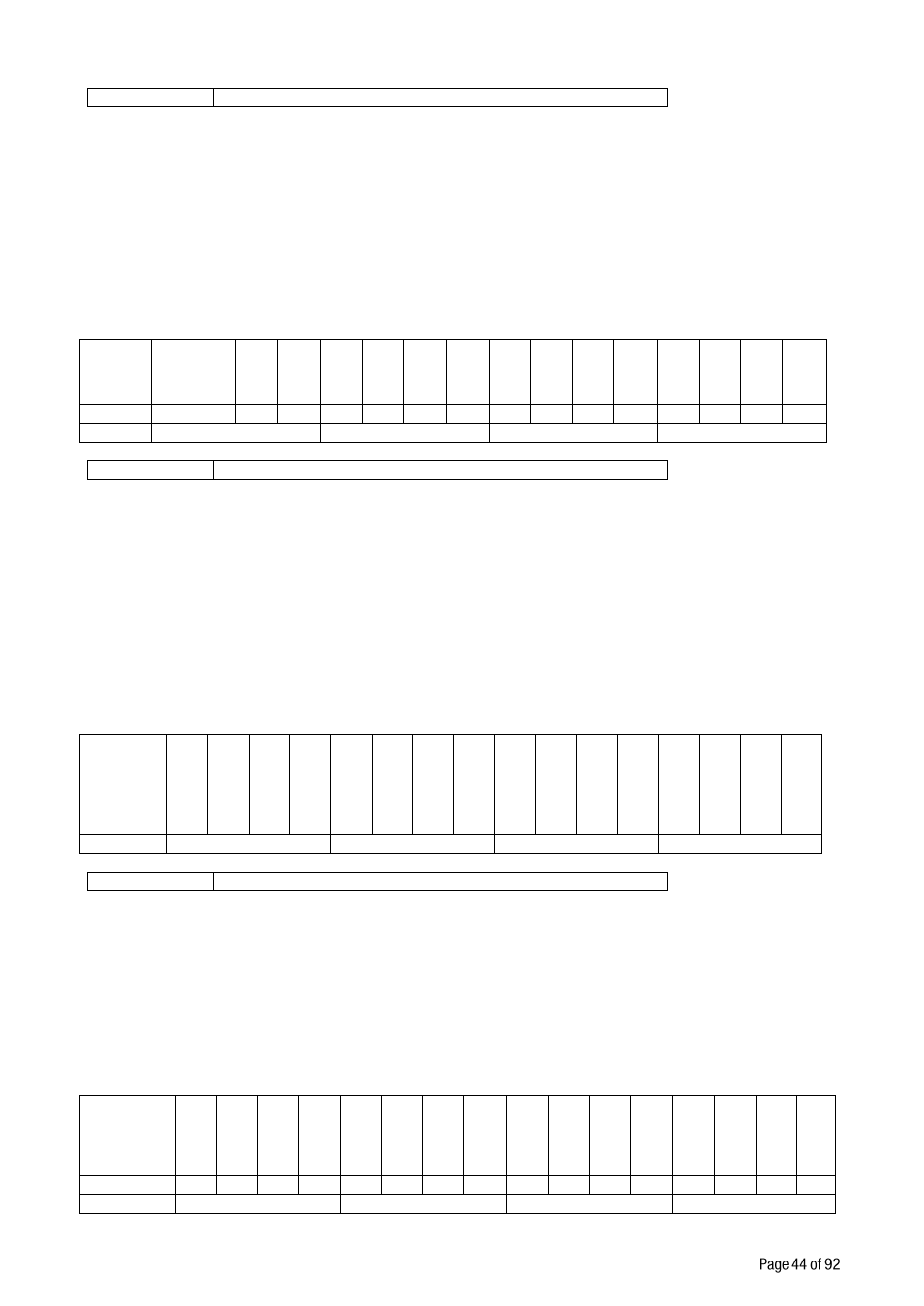
INPUT
S
IN
-16
IN
-15
IN
-14
IN
-13
IN
-12
IN
-11
IN
-10
IN
-9
IN
-8
IN
-7
IN
-6
IN
-5
IN
-4
IN
-3
IN
-2
IN
-1
Bit wise
0
1
0
0
0
0
1
0
1
0
0
1
0
1
1
0
ASCII
4
2
9
6
OUTPUT
S
O
UT
-16
O
UT
-15
O
UT
-14
O
UT
-13
O
UT
-12
O
UT
-11
O
UT
-10
O
UT
-9
O
UT
-8
O
UT
-7
O
UT
-6
O
UT
-5
O
UT
-4
O
UT
-3
O
UT
-2
O
UT
-1
Bit wise
0
1
0
0
0
0
1
0
1
0
0
1
0
1
1
0
ASCII
4
2
9
6
OUTPUTS
O
UT
-16
O
UT
-15
O
UT
-14
O
UT
-13
O
UT
-12
O
UT
-11
O
UT
-10
O
UT
-9
O
UT
-8
O
UT
-7
O
UT
-6
O
UT
-5
O
UT
-4
O
UT
-3
O
UT
-2
O
UT
-1
Bit wise
0
1
0
0
0
0
1
0
1
0
0
1
0
1
1
0
ASCII
4
2
9
6