1 entering the programming and calibration, Rogramming and, Alibration – Flintec FT-10xx User Manual
Page 22
FT-10 Smart Process Indicator, Technical Manual, Rev. 1.0, January 2014
5. P
ROGRAMMING AND
C
ALIBRATION
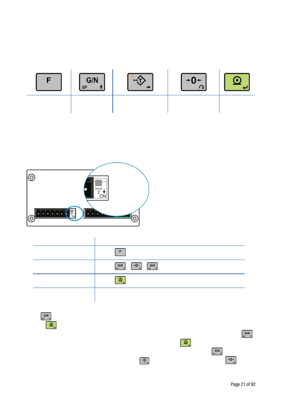
In this section you will find the programming and calibration procedure of FT-10 indicator according to your
application. The signs those take place on the lower right corner of the keys indicate the function of the keys
in programming menu. The basic meanings of these keys are given the table below.
Exit without saving Advancing next
parameter
Select the digit will be
changed
Changing parameter
value or increasing the
blanking digit
Enter
5.1 Entering the Programming and Calibration
There is a DIP switch on FT-
10’s rear side and its position should be “ON” ( downward ) to change the
metrological related parameters including calibration. There is no need to open the housing to change the
position of this DIP switch. If there is not set-up DIP switch on the instrument for industrial usage, its position
is always ON.
Figure 5.1 - The location of calibration DIP switch
Display
Operation
[123.456 kg]
Press
key until [ PASSWr ] prompts seen.
[PASSWr]
Press
+
+
keys sequentially.
[--- ]
Press
key for confirm.
[0-- ]
First block of Programming menu.
Programming and Calibration menu consist of main blocks which are shown as [X-- ] and sub-blocks. By
using
key you can reach next main blocks. After reaching the desired main block, you can get in by
pressing
key. As you enter the block you will reach the first sub-block in that main block. The sub-block
address will be seen on the display as [X0- ]. You can also search between the sub-blocks by using
key and reach the first parameter of the sub-block seen on the display by
key. The number of the
parameter comes on display as [XY0 ]. Again you can search between parameters by
key. For
entering numerical value in the parameters, press the
key to select the digit and press the
key the
change the value.