EVCO c-pro mega RACK User Manual
Page 24
C-PRO MEGA RACK & C-PRO GIGA RACK APPLICATION MANUAL
Page
24
* VDC=12.5 V Imax = 200 mA (as the sum of the current values for all VDC terminals).
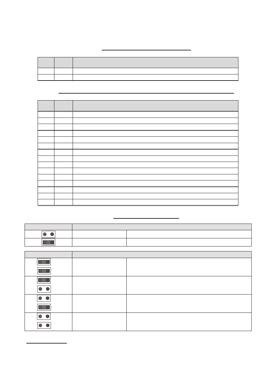
Card with 24 V AC/DC power supply
Conn.
Abbre
v.
Description
CA-1
VCC
card power supply input (24 VAC/DC)
CA-2
VCC
card power supply input (24 VAC/DC)
Other connectors (not present on the C-PRO EXP MEGA expansion unit)
Conn.
Abbre
v.
Description
JN-1
NC 9
relay No. 9 contact normally closed
JN-2
COM 9
relay No. 9 common connection
JN-3
NO 9
relay No. 9 contact normally open
JO-1
NC 10
relay No. 10 contact normally closed
JO-2
COM10
relay No. 10 common connection
JO-3
NO 10
relay No. 10 contact normally open
JP-1
COM11
relay No. 11 common connection
JP-2
NO 11
relay No. 11 contact normally open
JP-3
COM12
relay No. 12 common connection
JP-4
NO 12
relay No. 12 contact normally open
JP-5
COM13
relay No. 13 common connection
JP-6
NO 13
relay No. 13 contact normally open
JQ-1
DI9
No. 9 digital input 230 VAC
JQ-2
DI10
No. 10 digital input 230 VAC
JQ-3
CONHV
digital input common connection 230 VAC
Jumper and LED meanings
JMP3
CAN terminator
Jumper not inserted
Termination (120
?
) not inserted
Jumper inserted
Termination (120
?
) inserted
JMP4
Local CAN serial port baud rate selection
A
B
Jumper A inserted
Jumper B inserted
Baud rate = 20K
A
B
Jumper A inserted
Jumper B not inserted
Baud rate = 50K
A
B
Jumper A not inserted
Jumper B inserted
Baud rate = 125K
A
B
Jumper A not inserted
Jumper B not inserted
Baud rate = 500K
PLEASE NOTE:
The C-PRO MEGA RACK and the C-PRO GIGA RACK are configured by default to be able to
work with an expansion unit (with standard configuration) and with a user interface (with standard