3wiring diagram 3.1 connectors, 2 meaning of connectors – EVCO EPV4CBR Hardware manual User Manual
Page 9
EVCO S.p.A.
Vcolor | Hardware manual ver. 1.0 | Code 144VCOE104
page 9 of 38
3
WIRING DIAGRAM
3.1
Connectors
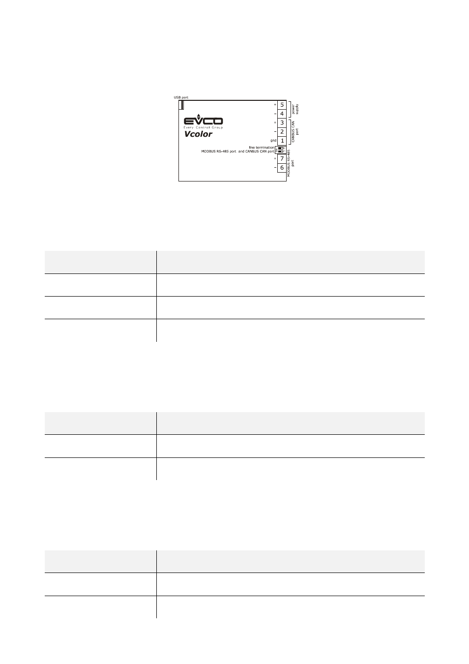
The following drawing shows the connectors of the devices.
3.2
Meaning of connectors
The following tables show the meaning of the connectors of the devices.
CANBUS CAN port
CAN port with CANBUS communication protocol.
Terminal
Meaning
1 ground
(gnd)
2
negative pole (-)
3
positive pole (+)
The CANBUS CAN port is the port to communicate with the programmable controllers and the I/O expansions belonging to the c-pro 3
range.
Power supply
Power supply device (24 VAC/DC not isolated).
If the device is powered in direct current, it will be necessary to respect the polarity of the power supply voltage.
Terminal
Meaning
4
negative pole (-)
5
positive pole (+)
MODBUS RS-485 port
RS-485 port with MODBUS communication protocol.
If the device works in browser modality, the communication protocol will be slave; if the device works in commander modality, the
communication protocol can be MODBUS master or MODBUS slave (this feature can be selected through the development environment
UNI-PRO 3).
Also consult the manual Modbus specifications and implementation guides available on the web site www.modbus.org.
Terminal
Meaning
6
negative pole (B / -)
7
positive pole (A / +)