17 relay panel operation, Gf-131 aerco control system (acs) – AERCO Control System (ACS) User Manual
Page 40
MC2: 04/23/13 Page 40 of 144
GF-131
AERCO Control System (ACS)
AERCO International, Inc. • 100 Oritani Dr. • Blauvelt, New York 10913 • Phone: 800-526-0288
Installation, Operation, and Maintenance Manual
OMM-0081_0D
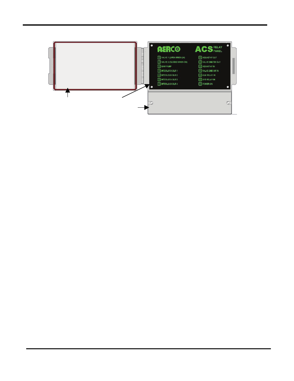
2.17 RELAY PANEL OPERATION
Figure 2-15: ACS Relay Panel Front Panel
The board operates basically as follows:
a) In the normal idle state, all the inputs, except one of the Valve End Switch In inputs, would
be open. As a result, the Aquastat Out would be open and the Valve End Switch Out would
be closed. All the relays except the Interlocks Relay will be in their unpowered state – DHW
Pump off, Valve 1 closed(N.C. powered), and Valve 2 open (N.C. powered). Since the
Valve End Switch Output would be activated, all the Interlocks relays will be activated and
all its contacts closed thereby enabling the Building Priority boilers to run if needed.
NOTE
If no Valve 2 (Sys Relay) is used, the Interlocks Relay connection
will not need to be used.
b) When the tank calls for heat and the Aquastat Input closes, the DHW Pump relay will
activate. The ACS will activate Valve 1 to close if it is not already closed. Once closed the
ACS will allow the DHW Priority boilers to run to provide heat to the tank.
If all the DHW Priority boilers are running at 100% for more than 2 minutes, the ACS will
open Valve 1 and close Valve 2 and activate the Building Priority boilers to help with DHW
heating.
When the Aquastat Input opens, the DHW Pump will turn off after some time delay (currently
60 seconds). The DHW Priority boilers will also shut down and Valve 1 will close and Valve
2 open.
c) Generally if any of the two valves is fully open and its Valve End Switch Input closes, the
Interlock relays will activate to allow the Building Priority boilers to run. When the Valve End
Switch Input opens, the Interlock relays will de-activate.
d) The Valve 1 Relay output is labeled such that the Normally Closed (N.C.) contact is Valve 1
Close and the Normally Open (N.O.) contact is Valve 1 Open. The Valve 2 Relay output is
labeled such that the Normally Closed (N.C.) contact is Valve 2 Open and the Normally
Open (N.O.) contact is Valve 2 Close. It is important to make these connections correctly. In
this way, the unpowered state of the relay panel will keep the valves in the default state with
Valve 1 closed and Valve 2 open.
Clear Plastic
Cover
Wiring Compartment Cover
Front Panel