Boilers, Gf-131 aerco control system (acs) – AERCO Control System (ACS) User Manual
Page 23
MC2: 04/23/13 Page 23 of 144
GF-131
AERCO Control System (ACS)
AERCO International, Inc. • 100 Oritani Dr. • Blauvelt, New York 10913 • Phone: 800-526-0288
Installation, Operation, and Maintenance Manual
OMM-0081_0D
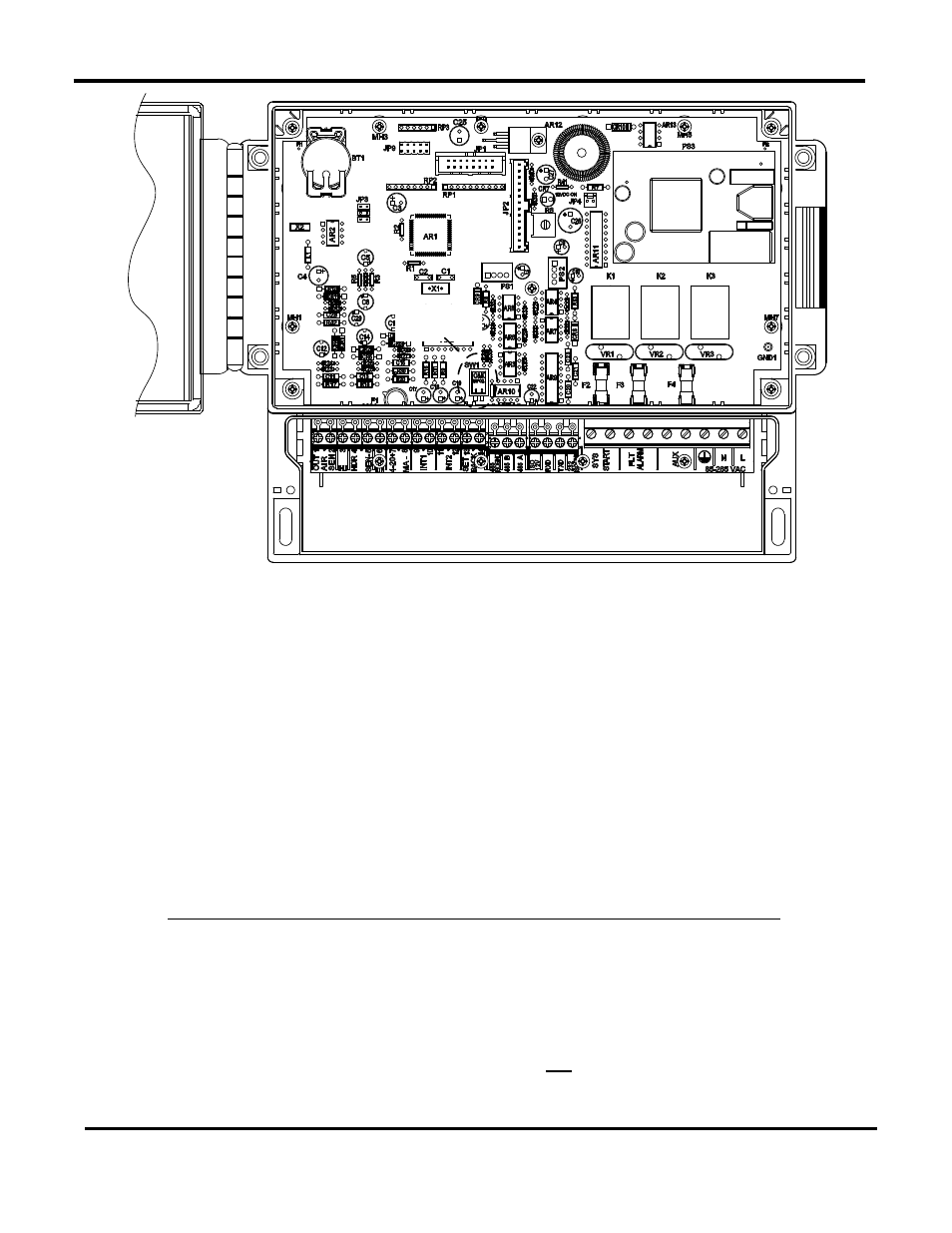
BIAS DIP
SWITCHES
NOTE:
THE BIAS DIP SWITCHES CAN BE ACCESSED
FROM THE WIRING COMPARTMENT WITHOUT
REMOVING THE FRONT PANEL FROM THE UNIT.
WIRING COMPARTMENT
Figure 2-6: Location of ACS DIP Switches
2.7 RS485 (MODBUS) WIRING, BIAS, AND TERMINATION AT
AERCO BOILERS
The RS485 wiring connections at the AERCO Boilers will depend on the type of AERCO Boilers
and Control Systems being used on the Modbus Network. Benchmark Series and KC1000
Boilers currently utilize C-More Control Systems. Modulex Series Boilers utilize Boiler Control
Modules (BCMs) with E8 Controllers.
2.7.1 RS485 Wiring, Termination& Bias for Benchmark Series and KC1000 Boilers
RS485 wiring connections are made at the RS485 terminals of each boiler’s I/O Box (
Figures 2-
7 or 2-8). However, activating bias and loop termination can be performed using one of two
available methods as described below in
Method A and on the following page in Method B.
Where possible,
Method B is the preferred method.
Method A: For Method A, the bias switches in the ACS are left in the deactivated (up) position.
Bias and termination are controlled at the boiler end of the RS485 loop by activating the bias
and termination DIP switches on the PMC board of the last C-More Control Box on the daisy-
chain. Refer to
sheet 1 of Figure 2-7 (Benchmark), or Figure 2-8 (KC1000) and proceed as
shown below: