8 sample rs485 (modbus) network diagrams, Gf-131 aerco control system (acs) – AERCO Control System (ACS) User Manual
Page 30
MC2: 04/23/13 Page 30 of 144
GF-131
AERCO Control System (ACS)
AERCO International, Inc. • 100 Oritani Dr. • Blauvelt, New York 10913 • Phone: 800-526-0288
Installation, Operation, and Maintenance Manual
OMM-0081_0D
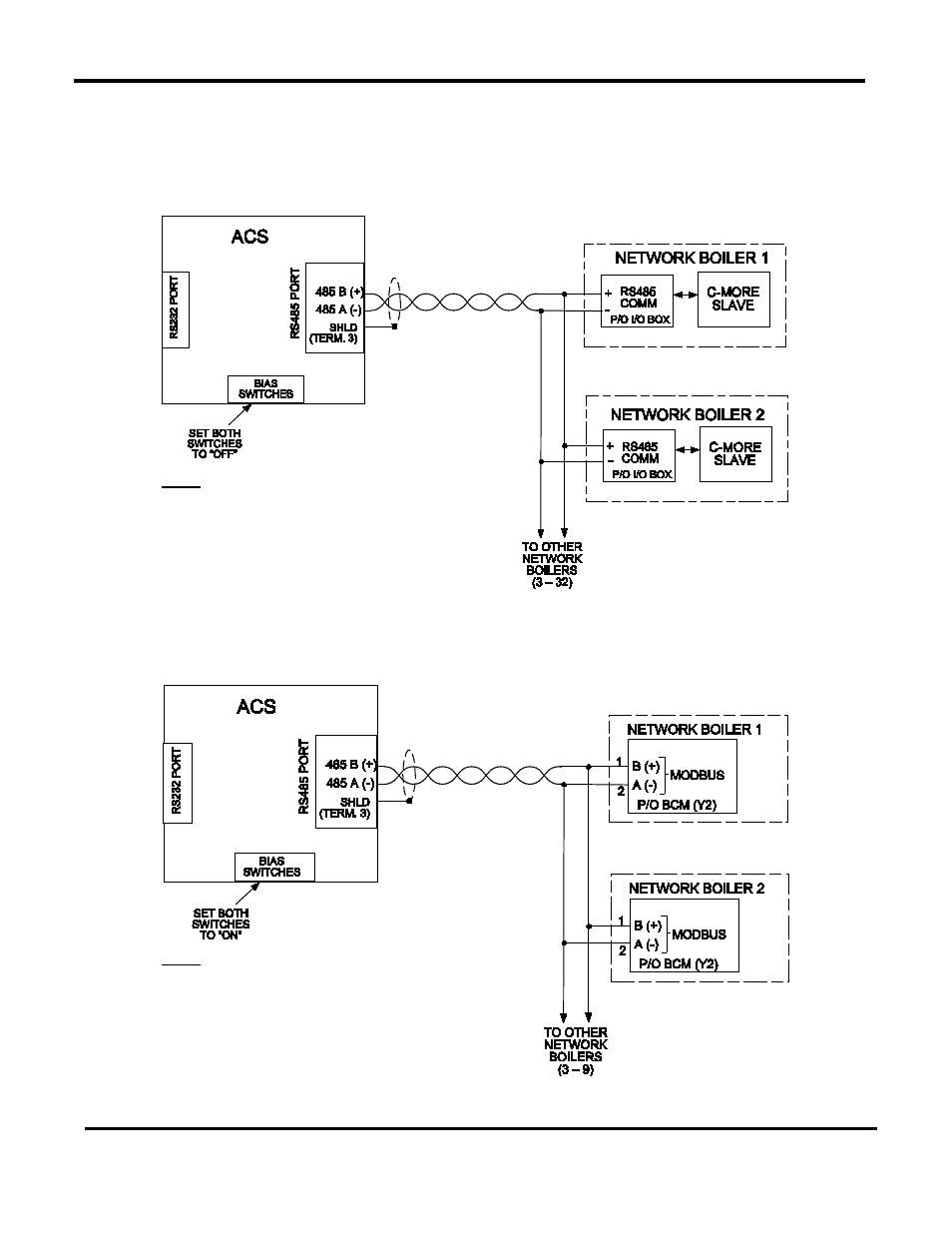
2.8 SAMPLE RS485 (MODBUS) NETWORK DIAGRAMS
Figure 2-10 shows a sample RS485 (Modbus) Network diagram with the ACS connected to
KC1000 or Benchmark Series Boilers equipped with C-More Control Systems.
Figure 2-11
shows a similar sample diagram with the ACS connected to Modulex Series Boilers equipped
with BCMs and E8 Controllers.
Figure 2-10: Sample RS485 (Modbus) Network For Benchmark or KC1000 Boilers
Figure 2-11: Sample RS485 (Modbus) Network For Modulex Series Boilers
NOTE
The last C-More slave on the RS485 loop
must have its termination resister (TERM)
and bias (BIAS1, BIAS2) DIP Switches
turned on. Refer to Section 2.7 of this
manual for details on activating bias and
termination.
NOTE
The last BCM slave on the RS485 loop
must have its termination resister (T)
activated. Refer to GF-115C for more
information.
The bias switches in the ACS should both
be turned to “ON”.