3 outdoor air sensor installation, Outdoor air sensor installation, Gf-131 aerco control system (acs) – AERCO Control System (ACS) User Manual
Page 20
MC2: 04/23/13 Page 20 of 144
GF-131
AERCO Control System (ACS)
AERCO International, Inc. • 100 Oritani Dr. • Blauvelt, New York 10913 • Phone: 800-526-0288
Installation, Operation, and Maintenance Manual
OMM-0081_0D
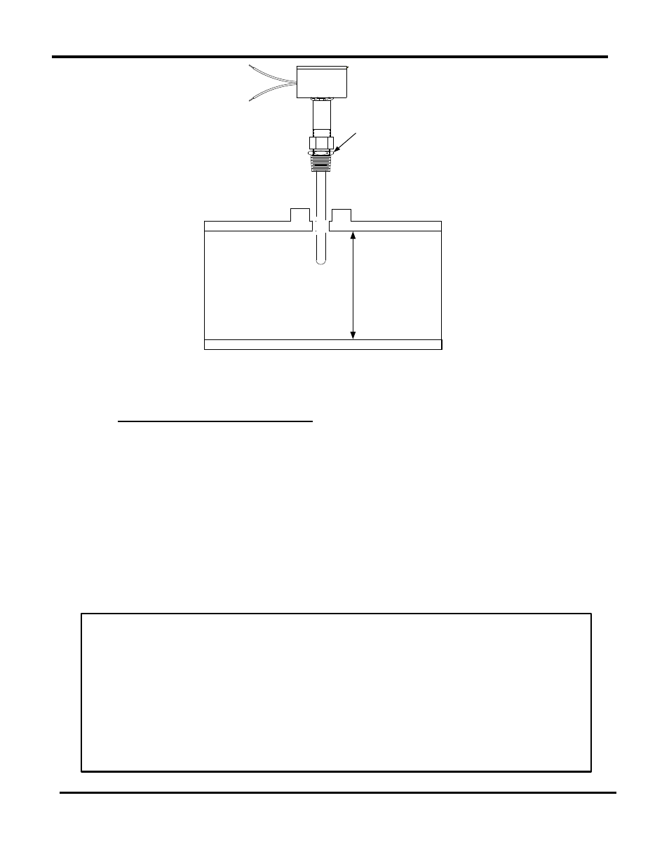
PROBE DEPTH MUST
EXTEND AT LEAST 2"
INTO PIPE
WELDED 1/2"
COUPLING OR
4"x4*x1/2"
T - FITTING
HEADER SENSOR
WITH THERMOWELL
INSTALLED
Figure 2-3: Header Sensor Installation Details
2.5.3 Outdoor Air Sensor Installation
The Outdoor Air Temperature Sensor (part no. GP-122662) is required when operating in the
ACS in the Outdoor Reset Mode (paragraph 4.2). An Outdoor Air Sensor Kit (part no. GM-
122781) is also available. This kit contains the Sensor (GP-122662) and a Mounting Bracket for
wall mounting. The Outdoor Air Sensor should be mounted on the North side of the building,
shielded from direct sunlight, and away from air intakes or outlets from the building. Shielded
pair 18 AWG cable (Belden # 8760 or equiv.) is recommended for sensor wiring. The Outdoor
Air Sensor can be mounted up to 600 feet from the ACS. See instructions below.
NOTE
The Outdoor Air Sensor is a thermistor type sensor. The Resistance vs.
Temperature Chart for this sensor is provided in
Appendix E. Length of
Header Sensor wire leads should not exceed 600 feet.
Outdoor Air Sensor Installation
1. Refer to
Figure 2-4 for a typical Outdoor Air Sensor installation.
2. Attach the sensor to the mounting bracket and secure the bracket in a suitable location
on the North side of the building.
3. Using shielded pair cable (Belden #8760 or equiv.), connect the two Sensor leads to
terminals 1 and 2 on the ACS. There is no polarity to observe when connecting the
sensor.
4. Terminate the cable shield at SHLD terminal 3 of the ACS. DO NOT terminate the shield
at the Sensor end of the cable.