3 site selection and mounting, Gf-131 aerco control system (acs) – AERCO Control System (ACS) User Manual
Page 16
MC2: 04/23/13 Page 16 of 144
GF-131
AERCO Control System (ACS)
AERCO International, Inc. • 100 Oritani Dr. • Blauvelt, New York 10913 • Phone: 800-526-0288
Installation, Operation, and Maintenance Manual
OMM-0081_0D
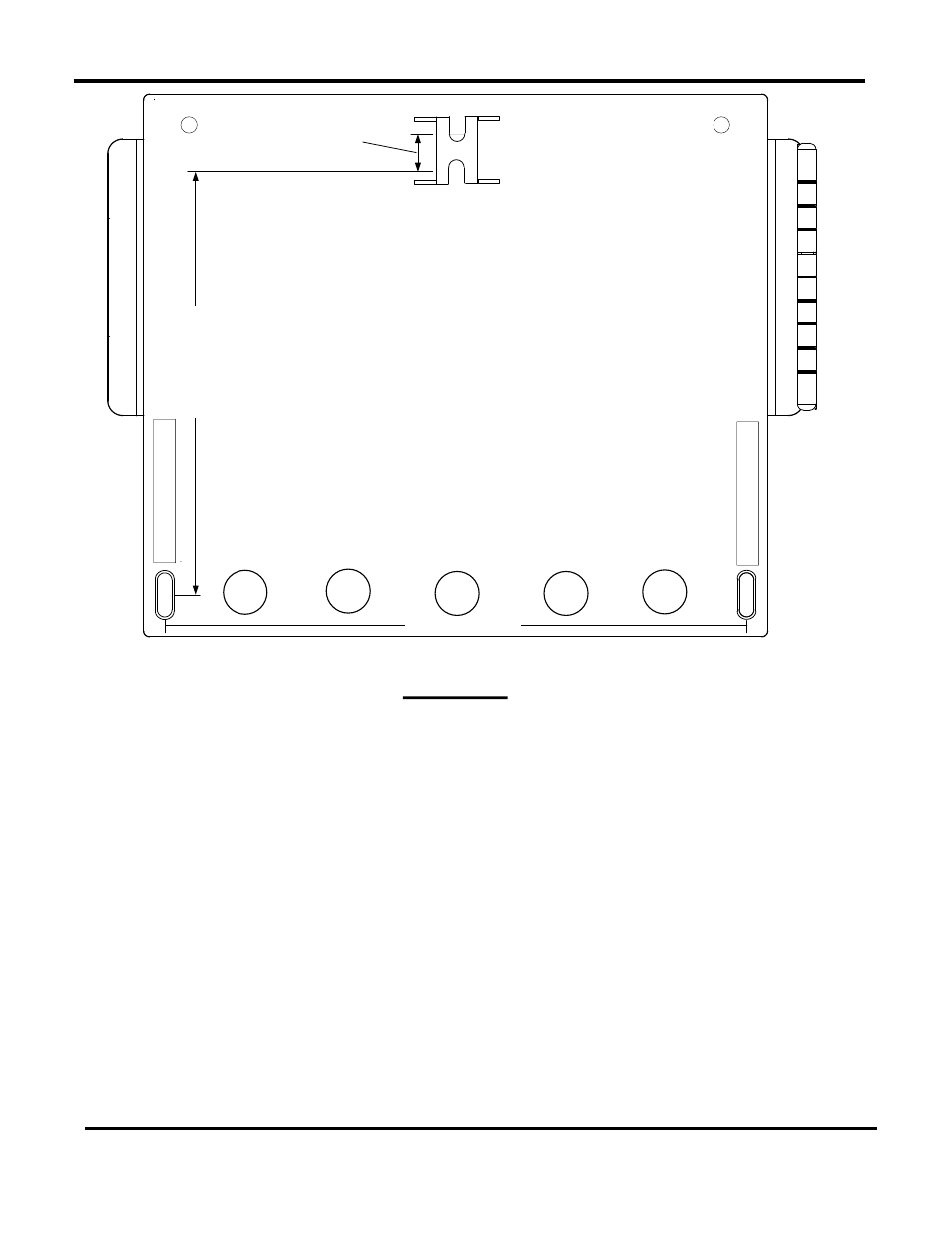
198 mm (7.8")
145
mm
(5
.7
")
15 mm
(0.6")
REAR VIEW
Figure 2-1: ACS Mounting Provisions
2.3 SITE SELECTION AND MOUNTING
All wiring connections to the ACS are made at the terminals located behind the wiring
compartment cover as shown in Figure 2-2. Run all wiring through the knock-outs provided on
the bottom surface of the unit. Shielded, twisted-pair cable should be used for sensor and
communication wiring. This wiring should be 18 to 24 AWG. Examples of suitable sensor and
communication wire are: Belden 9841, 8761, 3105A or equivalent. AC power wiring should be
14 to 18 AWG. The ACS wiring diagram is provided in Appendix E. Once mounting is complete
and the ACS is secured in place, loosen the two captive screws on the wiring compartment
cover using a Phillips screwdriver. Feed all wiring through the knock-outs provided on the
bottom of the panel.
NOTE
Refer to the wiring diagram provided in Appendix E when making all wiring
connections to the ACS.