2 rs485 wiring for modulex series boilers, Rs485 wiring for modulex series boilers, Gf-131 aerco control system (acs) – AERCO Control System (ACS) User Manual
Page 29: Bcm front view
MC2: 04/23/13 Page 29 of 144
GF-131
AERCO Control System (ACS)
AERCO International, Inc. • 100 Oritani Dr. • Blauvelt, New York 10913 • Phone: 800-526-0288
Installation, Operation, and Maintenance Manual
OMM-0081_0D
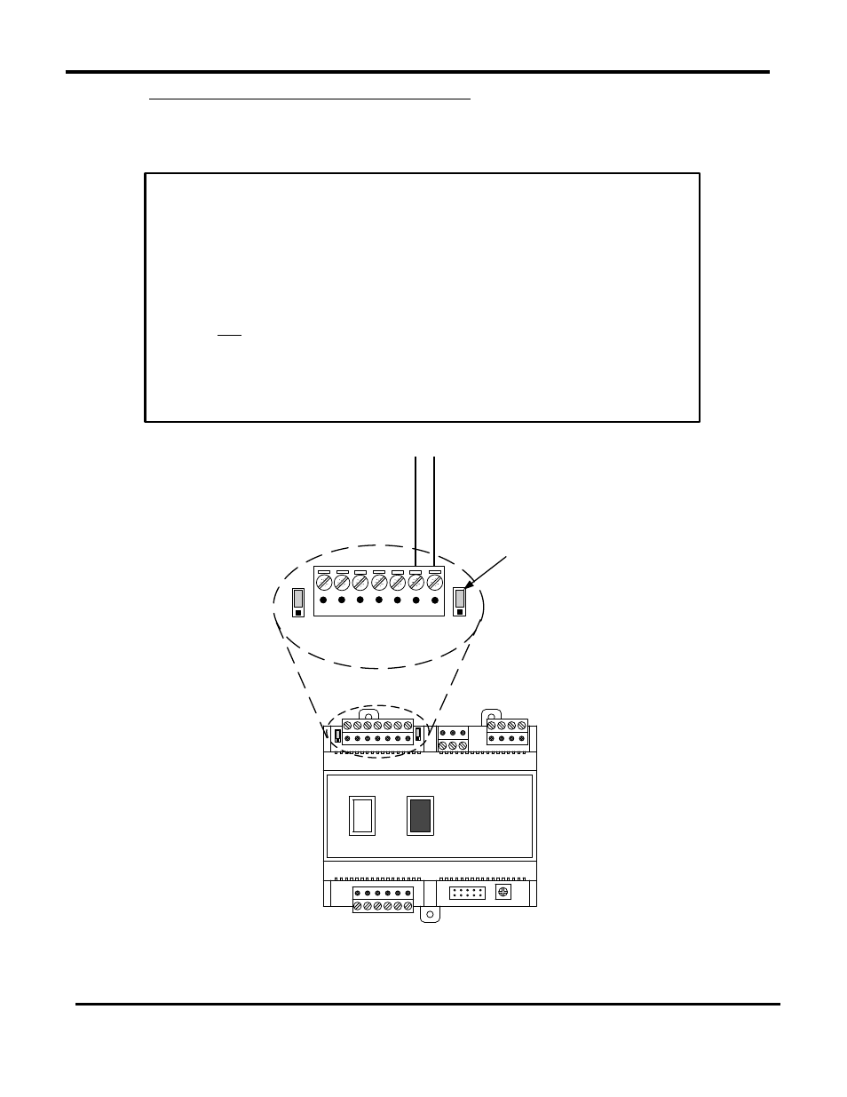
2.7.2 RS485 Wiring for Modulex Series Boilers
RS485 wiring connections are made at the MODBUS terminals of each Boiler’s BCM Module as
shown in
Figure 2-9. Connect the wiring as shown below:
Y2
Y3
Y4
Y1
SW1
A1
I
0
BCM FRONT VIEW
7 6 5 4 3 2 1
Y2
JP2
JP1
T
C
V
JUMPER
SHOWN IN
“TERMINATED”
(UP) POSITION
MODBUS B
(+)
MODBUS A
(-)
Figure 2-9: RS485 (Modbus) Wiring For Modulex Series Boilers
RS485 Wiring at Boiler BCM of Modulex Boiler(s)
1. Connect the positive lead to terminal
1 (MODBUS B +) of connector Y2.
2. Connect the negative lead to terminal
2 (MODBUS A -) of connector Y2.
3. DO NOT terminate the shields at the Boiler end of the RS485 loop.
Connect the shields of the incoming and outgoing leads together. The
RS485 loop shield should only be terminated at the ACS.
4. The last BCM in the daisy-chain must have the termination jumper
engaged as shown in
Figure 2-9.
5. The two ACS bias switches (
Figure 2-6) must be activated by placing them
in the down position.