Gf-131 aerco control system (acs) – AERCO Control System (ACS) User Manual
Page 130
MC2: 04/23/13 Page 130 of 144
GF-131
AERCO Control System (ACS)
AERCO International, Inc. • 100 Oritani Dr. • Blauvelt, New York 10913 • Phone: 800-526-0288
Installation, Operation, and Maintenance Manual
OMM-0081_0D
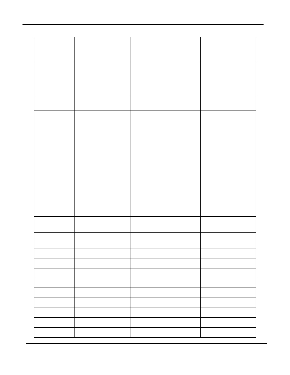
Table H-1: ACS Standard Input Register Address Mapping - Continued
Modbus Data
Address
Decimal (Hex)
Menu Item
Units and Range
Default/
Comments
55 (0x0037) Boiler 31 Status
(Net Boiler 31)
119 = Not On-Line
120 = On-Line But Not Fired
1–40 = Fired & Sequence
121 = On-Line But Disabled
122 = On-Line But Faulted
56 (0x0038) Boiler 32 Status
(Net Boiler 32)
Same As Above
57 (0x0039) I/O Status
00 to 255
Bit map of
Input/Output Status:
LSD:
Bit 0 = AUX Relay
Bit 1 = Fault Relay
Bit 2 = Sys Start
Relay
Bit 3 = Empty
MSD:
Bit 4 = Setback
Bt 5 = Interlock 2
Bit 6 = Interlock 1
Bit 7 = Empty
See Appendix A,
Table A-7.
58 (0x003A) Return Sensor Temp 40°F to 220°F
When Ret Sensor
Mode = Normal
59 (0x003B) Net Blr 1 Outlet Temp 40°F to 220°F
When Blr Cntl Type =
1 or 2
60 (0x003C) Net Blr 2 Outlet Temp 40°F to 220°F
61 (0x003D) Net Blr 3 Outlet Temp 40°F to 220°F
62 (0x003E) Net Blr 4 Outlet Temp 40°F to 220°F
63 (0x003F) Net Blr 5 Outlet Temp 40°F to 220°F
64 (0x0040) Net Blr 6 Outlet Temp 40°F to 220°F
65 (0x0041) Net Blr 7 Outlet Temp 40°F to 220°F
66 (0x0042) Net Blr 8 Outlet Temp 40°F to 220°F
67 (0x0043) Net Blr 9 Outlet Temp 40°F to 220°F
68 (0x0044) Net Blr 10 Outlet Temp 40°F to 220°F