1 system start relay, 2 fault alarm relay, 3 auxiliary relay – AERCO Control System (ACS) User Manual
Page 33: 13 4-20 ma wiring, 14 mounting and wiring the optional acs relay box, System start relay, Fault alarm relay, Auxiliary relay, Gf-131 aerco control system (acs)
MC2: 04/23/13 Page 33 of 144
GF-131
AERCO Control System (ACS)
AERCO International, Inc. • 100 Oritani Dr. • Blauvelt, New York 10913 • Phone: 800-526-0288
Installation, Operation, and Maintenance Manual
OMM-0081_0D
NOTE
The state of the SYS START, FLT ALARM and AUX Relays are
controlled by options contained in the Relay Menu described in
Chapter 3, paragraph 3.11.
2.12.1 System Start Relay
The state of the System Start (SYS START) relay contacts are controlled by the value set for
the SYS START TEMP and SYS START OPTION in the Relay Menu. The contacts are closed
either when the outdoor air temperature is less than the System Start Temperature (SYS
START TEMP) or when there is a load, or both. The default value for this temperature setting is
70°F. See
paragraph 4.5 for additional information.
2.12.2 Fault Alarm Relay
The state of the Fault Alarm (FLT ALARM) relay contacts are controlled by the option selected
for the FAULT ALRM RELAY, FAULT ALARM BLR and FAULT ALRM CLEAR in the Relay
Menu. Contact closure can be set to: ALL FAULTS, NO INTERLOCK, INTERLOCK 2 or
INTERLOCK 1. The default for this option is ALL FAULTS.
2.12.3 Auxiliary Relay
The state of the Auxiliary (AUX) relay contacts are controlled by the AUX RELAY CLOSE and
AUX RELAY OPEN options selected in the Relay Menu. Contact closure can be set to occur
either when all available boilers are at the 100% Fire Rate or for either when all boilers are at
100% Fire Rate or no boilers are available (all boilers faulted or turned off).
2.13 4-20 MA WIRING
The ACS can accept a remote 4 – 20 mA current signal representing a setpoint. This input is
fused internally at 0.63A. Connect the signal leads to the 4-20 + and 4–20 – terminals. Refer to
Chapter 4, paragraph 4.3 for Remote Setpoint programming using a 4 -20 mA input.
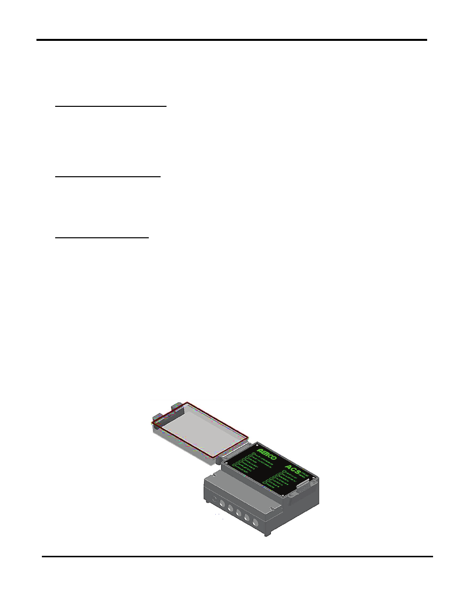
2.14 MOUNTING AND WIRING THE OPTIONAL ACS RELAY BOX
The ACS (Aerco Control System) Relay Panel is used in combination with the ACS to control up
to 2 isolation valves, boiler interlocks, and a Domestic Hot Water (DHW) pump in a Combination
heating plant where AERCO boilers are bring used for both Building Heat and Domestic Hot
Water heating.
Figure 2-13: AERCO Control System (ACS) Relay Box