Appendix h: acs modbus address assignments, Gf-131 aerco control system (acs) – AERCO Control System (ACS) User Manual
Page 127
MC2: 04/23/13 Page 127 of 144
GF-131
AERCO Control System (ACS)
Installation, Operation, and Maintenance Manual
OMM-0081_0D
AERCO International, Inc. • 100 Oritani Dr. • Blauvelt, New York 10913 • Phone: 800-526-0288
APPENDIX H: ACS MODBUS ADDRESS ASSIGNMENTS
IMPORTANT!
All Modbus addresses specified in this manual are written generically in
hexadecimal format. However, many Building Automation Systems utilize
another form of addressing where:
40001 is added to the generic address for a Holding Register address.
And
30001 is added to the generic address for an Input Register address.
Be sure to check the addressing scheme being used by the BAS that is
being interfaced to the ACS.
H.1 ACS CONTROLLER STANDARD INPUT REGISTER
ASSIGNMENTS
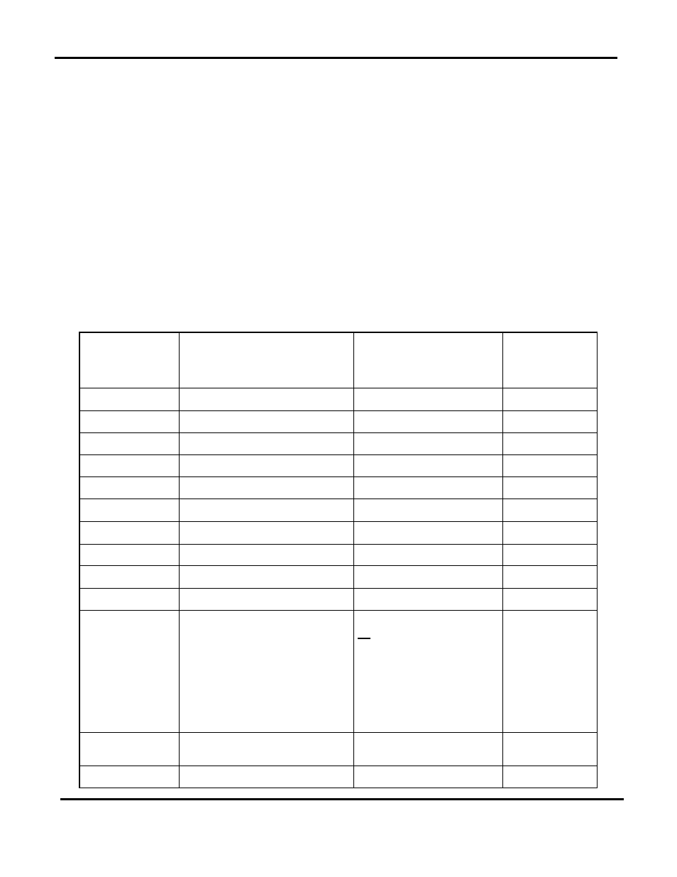
The Read Only Input Register assignments for the ACS are listed in Table H-1 which follows:
Table H-1: ACS Standard Input Register Address Mapping
Modbus Data
Address
Decimal (Hex)
Menu Item
Units and Range
Default/
Comments
0 (0x0000)
(Reserved)
1 (0x0001)
Header Temperature
40 to 220°F
2 (0x0002)
Outside Air Temperature
-60 to 120°F
3 (0x0003)
Indoor Air/Return Temperature
40 to 220°F
4 (0x0004)
Fire Rate Out
0 to 100% (out to boilers)
5 (0x0005)
Header Set Temperature
40 to 220°F
6 (0x0006)
Network Address
128 to 247
Default = 128
7 (0x0007)
Total Boilers Fired
0 to 32 (for ACS)
8 (0x0008)
Total Boilers On Line
0 to 32
9 (0x0009)
(Reserved)
10 (0x000A)
Fault/Message Code
0 to 65535
Bit:
0 = Outside Air Sensor
1 = Header Sensor Error
2 = Interlock 1 Error
3 = Interlock 2 Error
4 = Indoor Air Sensor Error/
Return Sensor Error
5 = 4-20mA Input Error
11 (0x000B) thru
15 (0x000F)
(Reserved)
16 (0x0010)
Lead Boiler Number
1 to 32