3 capacity of transmission buffer – KEYENCE N-400 User Manual
Page 71
63
Chapter 4 Multi-Drop Link Mode Control Procedure
4
•
The polling command can be received in either of the following formats:
[LF] can be added to the end of the command. When [ESC] is added to the
head of the command, data stored in the N-400’s receiving buffer can be
cleared.
•
Specify the read data format by selecting the “Header” and ”Delimiter” from the
following formats. (
➮
See p. 40.) The read data format can be changed.
Header: [ESC], [STX] None
Delimiter: [CR], [CR][LF], [ETX]
■
Setting manual polling mode
If ID numbers have not been registered with the N-400 setup software, manual
polling mode can be used. (When ID numbers have been registered, the N-400
automatically selects auto polling mode.)
Reference: Auto polling mode simplifies the host computer’s program since the
polling command is constantly sent to each BL series from the N-400, instead of
from the host computer.
4.2.3 Capacity of Transmission Buffer
■
Transmission buffer of N-400
The N-400’s transmission buffer can store up to 24 Kbytes (24576 characters).
The number of characters stored in the transmission buffer per piece of data is the
number of characters of the data (including the additional data such as number of
decodings) plus two characters indicating the data attributes.
Example 1
When the number of bar code digits is 10 (with no additional data)
24576 / (10 + 2) = 2048
The transmission buffer can store 2048 pieces of data.
Example 2
When the number of bar code digits is 20 (with no additional data)
24576 / (20 + 2) = 1117
The transmission buffer can store 1117 pieces of data.
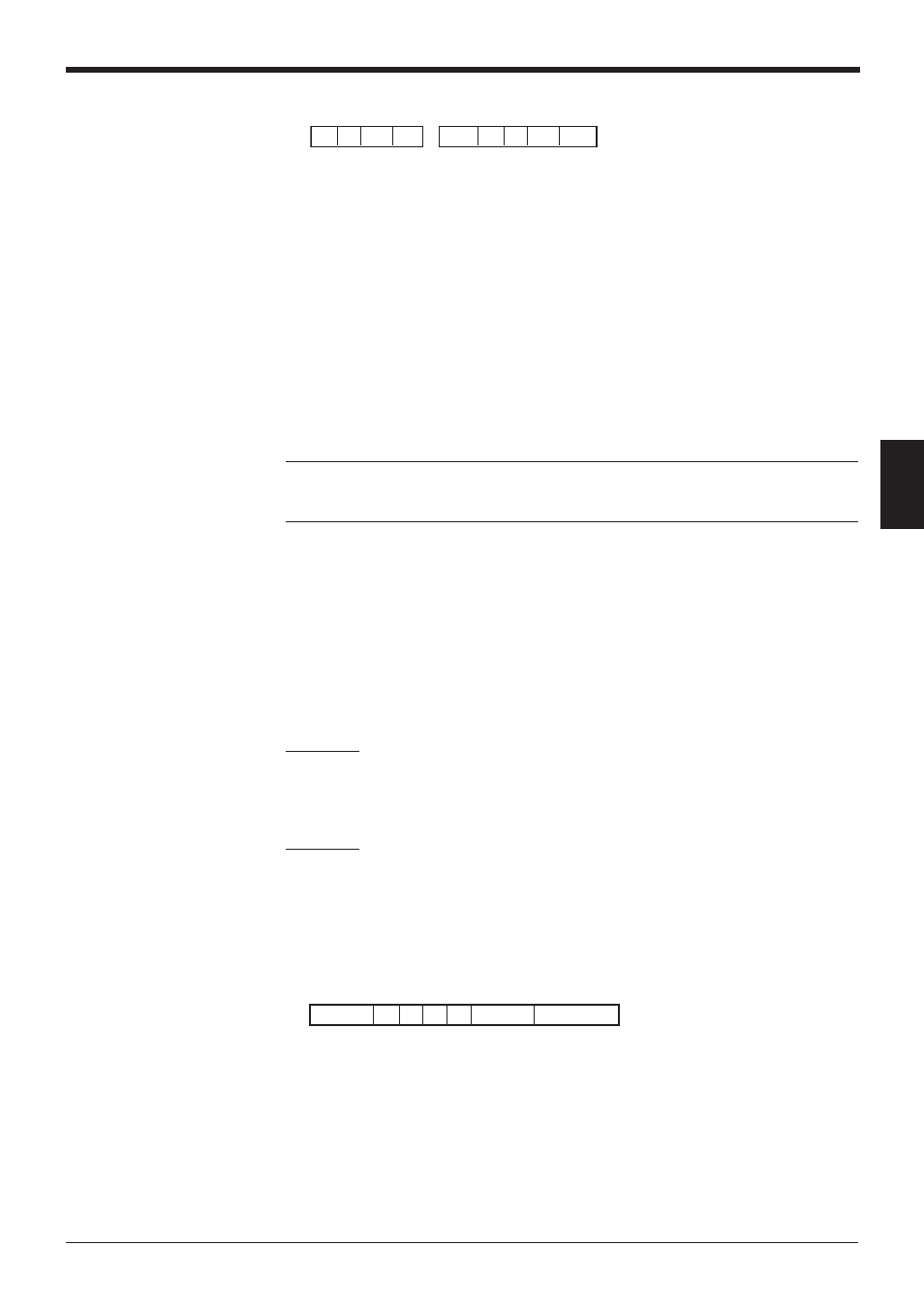
If the number of read data exceeds the buffer capacity, the N-400 sends back the
following “BUFFER OVERFLOW” error code to the host computer, and clears all
data stored in the transmission buffer. (The N-400 displays error code “97”.)
Header % P 00 –
OVER
Terminator
% P mm CR ,
%
STX
P mm ETX