2 device assignment in multi-head scan mode – KEYENCE N-400 User Manual
Page 121
113
Chapter 6 PLC Link
6
Operation when a connection error occurs
The power supply of the connected BL series is turned off:
•
The BL series is disconnected from the BL-U1 or N-48:
•
The cable is disconnected:
•
A communication error occurs:
If a communication failure occurs between the BL series and N-400 when the N-
400 is in the multi-drop link mode, the N-400 operates as follows:
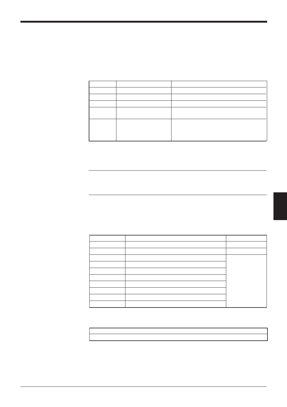
Address
Contents
Operation during a connection error
A + 00
“Write Data” flag
The flag is turned on as data are area written.
A + 01
Reserved area
A + 02
ID number
“FFFF” is written.
A + 03
Number of bar code
“1” is written. (This indicates that the number of
digits of the error code written in “A + 04” is “1”.)
A + 04
First digit of bar code data
During connection error: “N (ASCII codes: 4E)”
is written.
During communication error: “S (ASCII codes:
53)” is written.
+00
Data memory flag area
*
The above specifications apply to the multi-drop link mode only. The same
specifications do not apply to the multi-head scan mode.
*
The addresses subsequent to “A + 04” retain the previous data.
Note: If the N-400’s power supply is turned on before the BL series is turned on,
the N-400 starts communication before the BL series starts. This results in the
above connection error. Create programs that ignore the connection error when the
power supply is turned on in this case.
6.3.2 Device assignment in multi-head scan mode
These areas are used to store the bar code data read in multi-head scan mode.
Unlike multi-drop link mode, multi-head scan mode can control several BL series
like a single unit. Therefore, this mode provides only one data memory area.
■
Detailed description on device assignment
This area is used as a flag that indicates if bar code data has been stored in the
area.
The flag area can be used for the following two purposes:
Address
Description
Reference page
A + 00
Data memory flag area
pp. 113 and 114
A + 01
Reading trigger area
p. 114
A + 02
BL series ID number memory area
A + 03
Number of digits of bar code data
A + 04
1st digit of bar code data
A + 05
2nd digit of bar code data
p. 115
:
:
:
:
A + 06
3rd digit of bar code data
A + 258
255th digit of bar code data