3 device assignment, 1 device assignment in multi-drop link mode – KEYENCE N-400 User Manual
Page 116
Chapter 6 PLC Link
108
6
6.3
Device Assignment
The device assignment varies depending on whether the PLC link is used in multi-
drop link mode or in multi-head scan mode. The following sections describe the
device assignment in each mode.
6.3.1 Device assignment in multi-drop link mode
The data areas used to control the N-400 are provided in the PLC’s internal
memory (D areas or DM areas).
When a device head address is specified on the “PLC SETUP” screen of the N-400
setup software, the device numbers are automatically assigned based on the
specified head address.
■
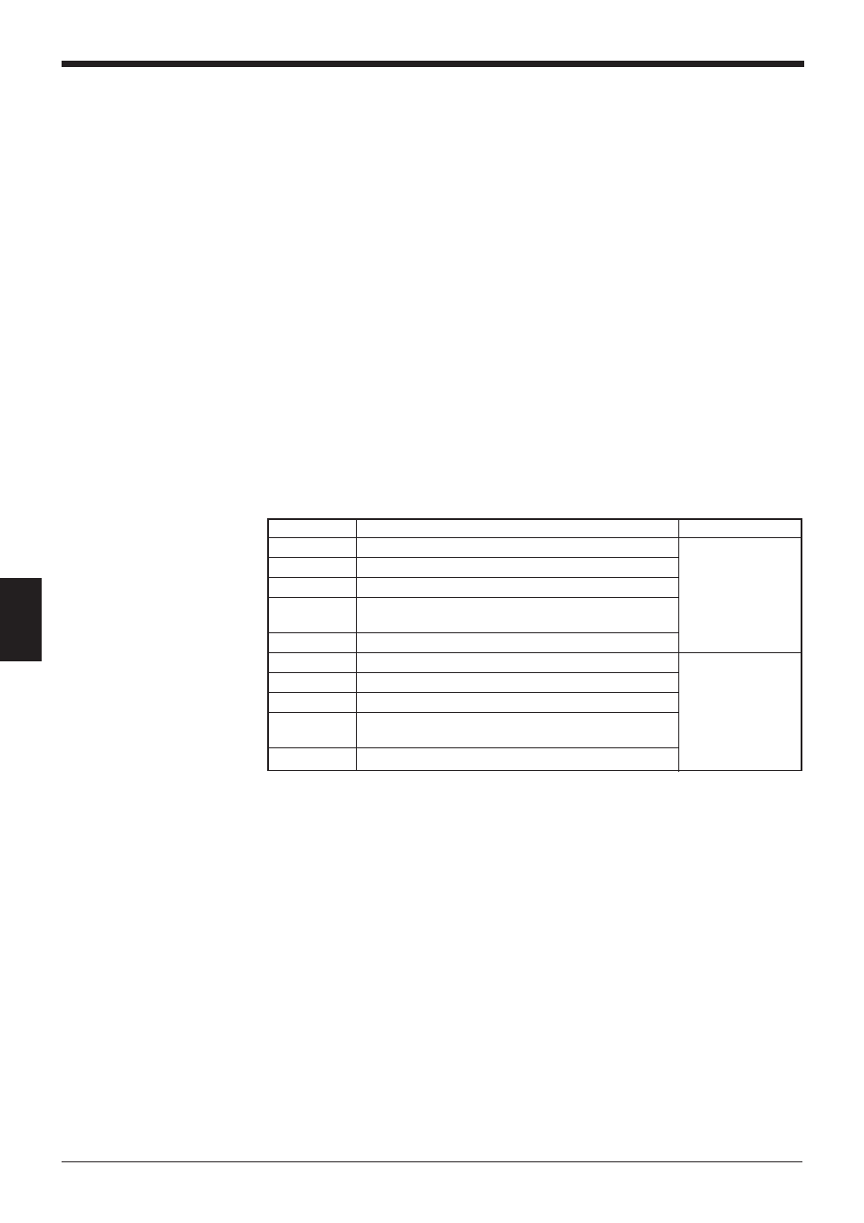
Data memory head address for each ID number and reading trigger areas
The addresses of “+00” to “+30” (based on the specified head address) indicate the
areas where the bar code data for each ID number is stored.
The addresses of “+31” to “+61” indicate the areas used to send a reading trigger
signal to the BL series. These areas are not assigned if you set “Reading trigger
input area” to “Disable” in the N-400 setup software. (In this case, these areas can
be used for other purposes.)
•
The “+00” to “+30” data memory head addresses can be set to the same
number. If the same head address is specified, data from all the BL series is
stored in the same area.
Address
Description
Reference page
+00
Data memory head address for ID No. 1
p. 108
+01
Data memory head address for ID No. 2
+02
Data memory head address for ID No. 3
:
:
:
:
+30
Data memory head address for ID No. 31
+31
Reading trigger area for ID No. 1
p. 108
+32
Reading trigger area for ID No. 2
+33
Reading trigger area for ID No. 3
:
:
:
:
+61
Reading trigger area for ID No. 31