KEYENCE N-400 User Manual
Page 123
115
Chapter 6 PLC Link
6
When a photoelectric sensor for trigger input is connected to the BL series, do not
use this area.
Specify this area as follows:
• Start reading (Trigger ON): 0001
• End reading (Trigger OFF): 0000
Note: Specify this area as “0000” while the BL series is not reading bar code data.
•
The ID number of the BL series that read the data is stored in the +02 address.
The number of data digits is stored in the +03 address as binary data.
•
The read bar code data is stored in the +04 to +258 addresses using the ASCII
codes (Hexadecimal numbers in two digits) by the digit. (See the ASCII code
table on p.134.)
•
If a read error occurs, the “ERROR” code is stored in the corresponding area.
(The read error code can be easily changed according to the BL series’ setting.)
•
If the buffer overflow error occurs with the BL series, the “OVER” code is stored
in the corresponding area.
Note: These data areas accept up to 255 digits. However, the BL series can read
only 32 digits. Therefore, all of the areas for 255 digits are not used for the N-400.
Only the areas corresponding to the number of the data digits are used.
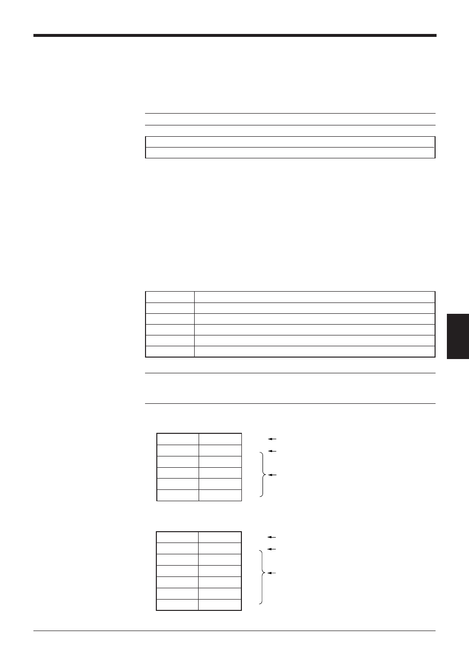
Example: When the BL series reads bar code data as “KE12”:
Example: When a read error (ERROR) occurs:
+02 to +258
Data (ID number, number of digits, data) memory area
A+02
ID number (1 to 31)
A+03
Number of digits of bar code data (1 to 255)
A+04
1st digit of read data
A+05
2nd digit of read data
:
:
A+258
255th digit of read data
+ 02
12
+ 03
4
+ 04
$004B
+ 05
$0045
+ 06
$0031
+ 07
$0032
ID number
Number of digits
Specified by ASCII codes
(hexadecimal numbers)
"K"
"E"
"1"
"2"
+ 02
1
+ 03
5
+ 04
$0045
+ 05
$0052
+ 06
$0052
+ 07
$004F
+ 08
$0052
ID number
Number of digits
Specified by ASCII codes
(hexadecimal numbers)
"E"
"R"
"R"
"O"
"R"