KEYENCE N-400 User Manual
Page 100
Chapter 5 Multi-Head Mode Control Procedure
92
5
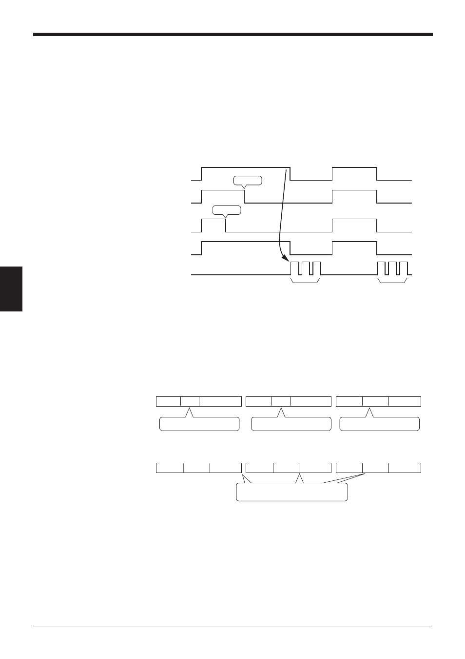
Header 1234
Terminator
Header ABC
Terminator
Header ERROR Terminator
Header ERROR Terminator
Header ERROR Terminator
Header ERROR Terminator
The BL series with ID No. 1
reads bar code data as “1234”.
The BL series with ID No. 2
reads bar code data as “ABC”.
Read error occurred in the BL
series with ID No.3.
Read errors have occurred in the BL series
with ID Nos. 1, 2 and 3.
•
In “Multi 1” reading mode, all connected BL series units read bar code data
while the trigger input is ON, and send the individual data immediately after
reading it.
•
A BL series that causes a read error sends no data.
•
If all of the connected BL series cannot read bar codes while the trigger input is
ON, a read error code is output.
“Multi 2” reading mode
The following timing chart shows the case in which three BL series are connected.
•
In “Multi 2” reading mode, all connected BL series read bar code data while the
trigger input is ON, and send the individual data after the trigger input is turned
OFF, starting with the smallest ID number.
•
In “Multi 2” reading mode, every connected BL series sends a piece of data. A
BL series which causes a read error sends an error code.
Example: In the above timing chart, the communication output is as follows:
Communication output (A):
Communication output (B):
Reading
Reading
A
B
1
2
3
1
2
3
ID•••
Timing input
Light source of
BL series with
ID No. 1
Light source of
BL series with
ID No. 2
Light source of
BL series with
ID No. 3
Communication
output